 Nederlands



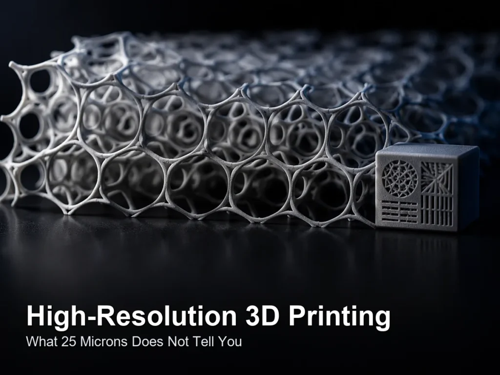
TL;DR — Layer height describes one direction and a machine setting; it does not tell you the smallest hole that will stay open, the thinnest wall that will stand up, or the tolerance the finished part will hold. Those are three different limits, and on a real part the tolerance number is usually the largest of them, which is why a “25 micron” machine can print a feature it cannot dimension.
Key Takeaways
- Resolution is about forming a feature. Tolerance is about where that feature lands in space. A printer can do both well and still put your 0.1 mm detail two tenths of a millimetre away from where the drawing says it belongs.
- Additive tolerance is normally written as a fixed term plus a percentage of the span, so the number grows with the part. Ideal Pro’s published figures are ±0.2 mm base on SLA, MJF and FDM and ±0.3 mm on SLS, with a 0.15 to 0.35 percent adder beyond 100 mm.
- Minimum wall is a process limit and a service limit at the same time. The published minimum is the thinnest thing that will build, not the thinnest thing that will survive insertion, cleaning or a fixture clamp.
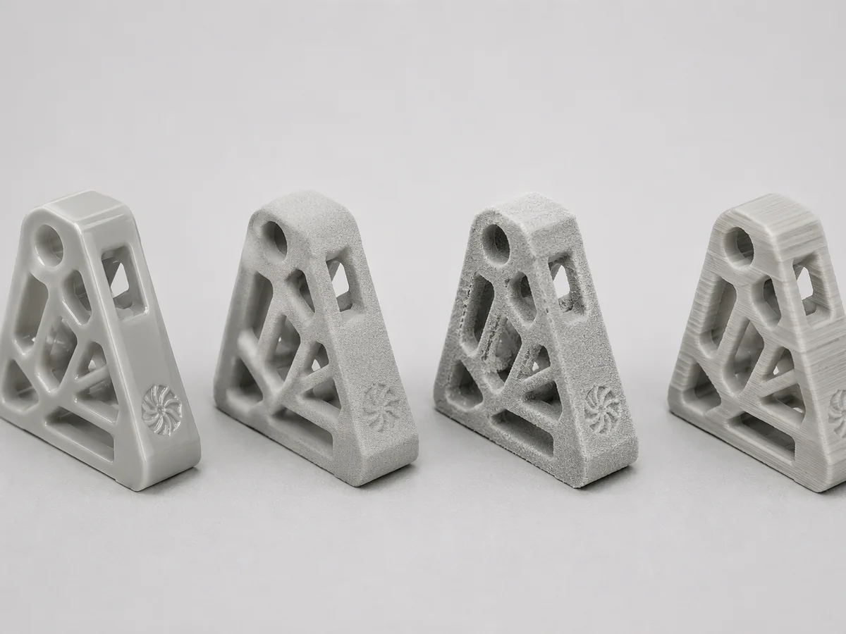
- Finishing spends detail budget. Paint and plating add film thickness into recesses; polishing removes material from crests. Judge a fine feature after the full finishing sequence, because that is the state it ships in.
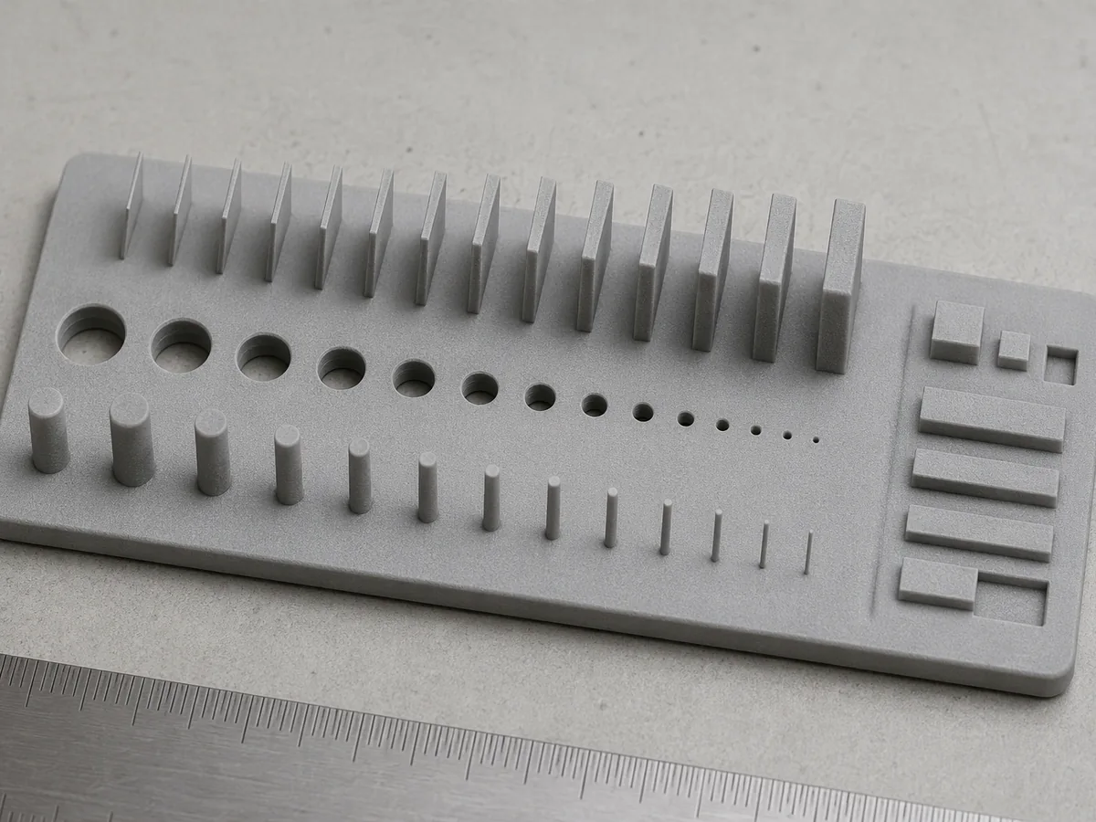
- Prove the detail on a coupon before the part. One small plate carrying a wall ladder, a hole ladder and a pin ladder, printed in the intended material and put through the intended finishing, answers more than any specification sheet.
Why Trust This Guide
Author: Alex Yu, co-founder of Ideal Pro — 20+ years across mold-making, injection molding and additive manufacturing, with SLA, MJF, SLS, FDM and DMLS capacity running beside tooling and production molding. We quote printed parts and then have to make the same geometry in a mould, which gives us an unusually direct interest in what a prototype promised and what a mold will actually deliver.
Method: every process figure attributed to Ideal Pro comes from our published capability table at /3d-printing/, so it can be checked against the machines that produced it. Worked examples use those figures with the arithmetic shown, so you can substitute your own span. Where a value is an industry-typical range rather than our measurement, it says so.
Scope: fine features in polymer additive — walls, pins, holes, channels, lettering and texture — plus the tolerance and finishing consequences that decide whether the feature is usable. Metal powder-bed is covered only where the reasoning is shared.
What Does “High Resolution” Actually Describe?
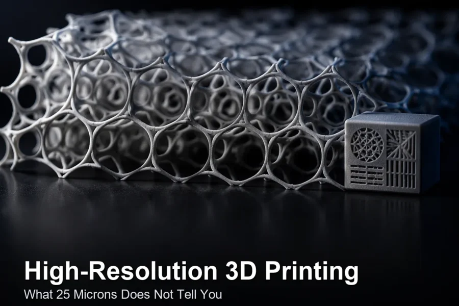
A machine advertised at “25 micron resolution” is usually quoting a layer-height setting. That is one direction, and it is a setting rather than a capability. To know what will arrive, you need three separate numbers.
| Term | What it measures | What sets it | What it does not tell you |
|---|---|---|---|
| Z resolution (layer height) | Vertical step size | Slicer setting within the machine’s range | Whether a 0.1 mm feature survives, or where it lands |
| XY resolution | Detail in the build plane | Laser spot or projected pixel size; for FDM, the deposited bead width | Material behaviour, cure spread, cleaning access |
| Minimum feature size | Smallest geometry that reproduces usefully | The forming physics plus post-processing | Tolerance, strength in service |
| Dimensional tolerance | Where measured dimensions land | Machine accuracy plus shrinkage plus span | Whether the feature exists at all |
The rows are independent. A process can have a 20 µm layer height, reproduce a 100 µm raised line, and still hold only ±0.2 mm plus a span term on the position of that line. Three of those four statements are usually on the brochure and one is not.
Why Doesn’t a 25 Micron Layer Height Give Me a 25 Micron Feature?
Because the mechanisms do not stop at the boundary you asked for.
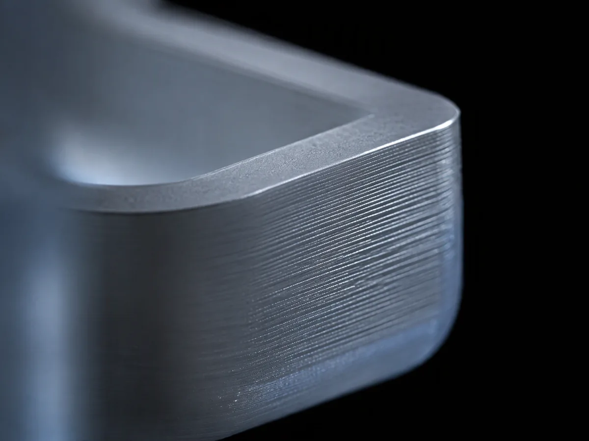
In vat photopolymer processes the cure does not halt at the intended edge. Light spreads below the surface and a few microns sideways, so a narrow line cures wider than drawn and a small hole cures narrower. Shrinkage on post-cure then moves both. This is why fine-detail resin work is specified against a compensation the machine cannot know about: your resin, your exposure, your post-cure.
In material extrusion, the tool is a bead. Its width is the floor on any horizontal feature, and a thinner layer does not make the bead narrower — that is why reducing layer height improves the staircase on a curved surface while leaving hole diameter and wall width untouched. Ask for a 0.2 mm hole with 0.1 mm layers and you are asking a 0.4 mm bead to outline something smaller than itself.
In powder processes the boundary is heat. Sintering or fusing spreads into neighbouring powder, so an edge is a transition zone rather than a line, and a narrow gap can bridge. Depowdering then sets a second, harder limit: the passage must give the unfused powder a route out.
The practical translation: specify the feature, and let the process tell you the size it needs. Do not derive feature limits from a layer-height number.
How Small Can Each Feature Actually Get?
Published minimums for Ideal Pro’s processes, taken from the capability table, with what each figure is really guarding:
| Feature | SLA | MJF | SLS | FDM | What decides it |
|---|---|---|---|---|---|
| Minimum wall, unsupported | 0,5 mm | 1.0 mm | 0.7 mm (PA12) to 2.0 mm (carbon-filled) | 0.8 mm | Forming limit first, then handling and clamping |
| Minimum wall, supported both sides | 0,4 mm | n/a as published | n/a as published | 0.6 mm | Neighbouring geometry carries the load |
| Layer height | 20 to 100 µm | ~80 µm | 20 to 100 µm | 100 to 300 µm, typically 200 µm | Surface stair-step, not feature width |
| Holes and passages | Cure spread plus wash-out access | Depowder route | Depowder route, longer passages worse | Bridging and bead width | Access, not the forming limit |
The published minimum is the thinnest section that will build. The size you should draw is the thinner of that and the size that survives what the part does afterwards: insertion, cleaning, a clamp, a screw torque.
Three rules follow from the table. A divider joined to surrounding walls has support along several edges and can be thinner than a free-standing wall of the same section. A pin’s usable diameter grows with its height, because height gives a sideways force a longer lever. And a hole is a different problem class from a solid feature: a pin only has to form, while a hole has to resist material growing into the space you wanted and then be cleanable.
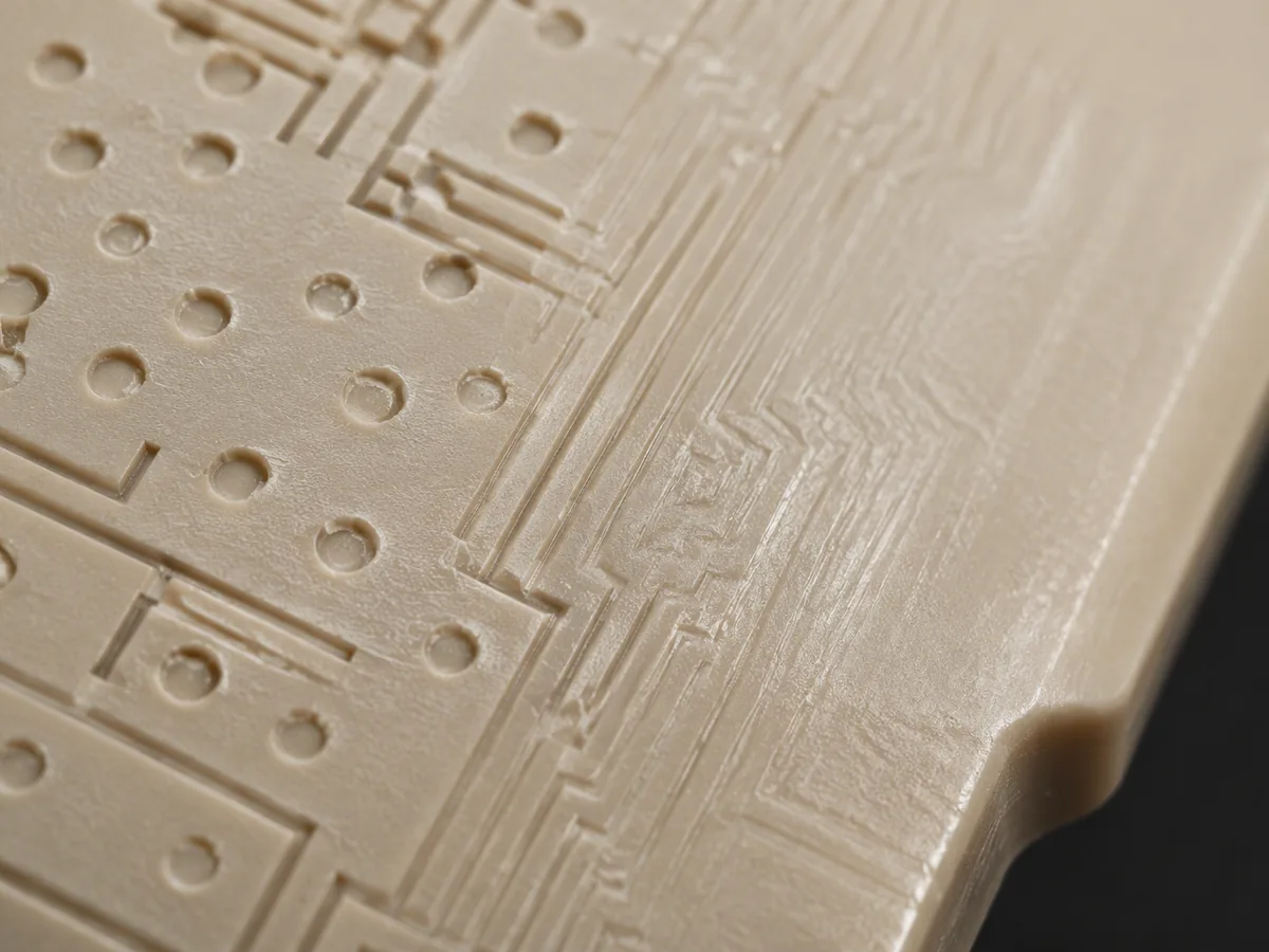
For lettering the limit sits on the stroke, not the letter height. A 6 mm capital with 0.15 mm serifs loses them; a 3 mm letterform with 0.4 mm strokes and open counters reads cleanly. Raised detail survives smaller than recessed detail, because a raised line only has to stay attached while a recess has to stay open.
What Tolerance Will My Part Actually Hold?
This is the number that decides whether fine detail is usable, and it is almost never the number on the brochure. Additive tolerance is normally written as a fixed term plus a percentage of the span once the part exceeds a threshold. Using Ideal Pro’s published figures — base ±0.2 mm on SLA, MJF and FDM, ±0.3 mm on SLS, with 0.15, 0.25, 0.35 and 0.20 percent respectively applied beyond 100 mm — the arithmetic runs like this:
tolerance = base + (percentage × span beyond the threshold)
| Span of the controlled dimension | SLA (±0.2 mm + 0.15%) | MJF (±0.2 mm + 0.25%) | SLS (±0.3 mm + 0.35%) | FDM (±0.2 mm + 0.20%) |
|---|---|---|---|---|
| 60 mm (base term only) | ±0.20 mm | ±0.20 mm | ±0.30 mm | ±0.20 mm |
| 120 mm | ±0.23 mm | ±0.25 mm | ±0.34 mm | ±0.24 mm |
| 200 mm | ±0.30 mm | ±0.35 mm | ±0.45 mm | ±0.30 mm |
| 300 mm | ±0.35 mm | ±0.45 mm | ±0.60 mm | ±0.40 mm |
| 600 mm | ±0.65 mm | ±0.95 mm | ±1.30 mm | ±0.80 mm |
Now put that next to the feature sizes from the previous section. A 0.1 mm raised line is a forming result. On a 300 mm SLA housing it will form crisply and sit somewhere inside a ±0.35 mm position band. If the line is cosmetic, nobody cares and the process is right. If the line is a sealing land, a locating edge or a snap-fit datum, that band is three times the feature you just paid to resolve.
Resolution says the feature will exist. Tolerance says where it will be. On a large part with fine detail, the tolerance term is the one that will surprise you, because it grows with the part while the feature stays the same size.
Two consequences worth designing around. First, the controlled dimension should be measured between features that are close together, because a span term punishes long distances; a hole pattern inside a 30 mm boss lives in a much friendlier band than two bosses 400 mm apart. Second, if a feature genuinely needs better than the process holds, the answer is a secondary operation on that feature, not a finer layer height. Layer height does not move a span term.
Which Process Do I Choose When the Detail Also Has to Work?
Start from the feature that would make the part fail, then ask what else that choice commits you to.
| Proces | Best at | Detail limit is set by | Give-up |
|---|---|---|---|
| SLA and other vat photopolymer | Fine lettering, textures, smooth appearance models, transparent parts | Cure spread, wash-out access, support marks | Long-term heat and UV behaviour depend heavily on the resin; some grades creep |
| MJF | Tough nylon parts in batches, balanced mechanics, living hinges | ~80 µm layers and a grain-like surface; fine detail blurs at the edges | Minimum wall around 1 mm; grey powder-finish surface unless finished |
| SLS | Complex functional geometry, no supports, end-use nylon parts | Heat spread and the depowder route for internal passages | Widest published tolerance of the four; rough as-built surface |
| FDM (industrial, engineering filaments) | Large fixtures, jigs, big stiff parts, the widest material list | Bead width and unsupported spans | Visible layer structure and the weakest Z-direction strength |
| DMLS / metal powder bed | Working metal geometry, integrated cooling, tool inserts | Melt-pool size, roughness, and residual stress in the plate | Cost, and post-processing you should plan rather than discover |
The mistake worth naming is buying resolution you do not need. If the acceptance feature is a 3 mm snap that has to flex fifty times, a powder process in PA12 answers the question, and a fine-detail resin that cannot take the strain answers nothing. Material behaviour and part function outrank layer height every time the part has a job.
How Much Detail Does Post-Processing Destroy?
Enough that it should be designed in, not discovered at delivery.
- Washing and support removal act on the delicate features first. Prolonged solvent softens thin walls; breaking a support off a 0.2 mm logo leaves a witness you then have to sand, which is a second hit on the same feature.
- Sanding and blasting round crests. A shallow engraved line loses depth on every pass, and a bead-blasted surface gains a matte texture that is itself a few microns deep.
- Paint bridges and fills. A decorative coat typically adds tens of microns of film, which is a fraction of a millimetre on a flat face but a multiple of the depth of a shallow recess.
- Galvanisch verzinken deposits metal and follows the topography it finds, so it preserves a crisp edge but cannot rescue a blurred one, and it adds its own thickness to every dimension.
Our own published finishing figures are the reason to write this down: precision polishing is specified to bring roughness below Ra 0.8 µm, which is a surface-quality number and not a feature-depth number. The polish removes material from the high points, so a 0.15 mm recess does not come out 0.15 mm deep. If a texture has a depth requirement, put the requirement on the finished condition and ask how it will be verified.
The rule that saves arguments: evaluate critical detail after the complete finishing sequence, in the state the part ships in. A part accepted from the machine and rejected after paint is a specification gap, not a quality failure.
How Do I Prove the Detail Before Committing the Whole Part?
Print a coupon. One small plate carrying the feature classes you actually depend on, in the intended material and machine, followed by the intended finishing, replaces a specification sheet with a measurement.
| Ladder | Steps to include | What “passed” means |
|---|---|---|
| Wanddikte | Sit either side of the published minimum, for example 0.4 / 0.5 / 0.6 / 0.8 mm, one free-standing and one joined to a back wall | Survives removal from the plate, cleaning and handling with no break and no measurable bow |
| Hole diameter | A run of through-holes at different diameters, with passage length varied as a second axis | Finished diameter measured with a pin gauge, and the long passage verified clear rather than assumed clear at the entrance |
| Pin height and diameter | Two or three heights at the same diameter, then the same height with a thicker base | Stands up after cleaning, and survives the insertion force the real part will see |
| Text and texture | Two letter heights with different stroke widths, one raised and one recessed | Readable after the planned finish, judged against the acceptance sample you keep |
Specify the coupon as a deliverable and measure it. That gives you a real tolerance for the geometry you care about instead of a brochure figure, and it settles the hole-compensation question with your supplier before it becomes a rejected batch. It costs a fraction of one build and it is the difference between a documented process window and a hope.
Will My Printed Fine Detail Survive the Move to Molding?
Not automatically, and this is where a printed part that looks perfect creates the most expensive surprise. A mould has constraints a print does not: it must open, the part must eject, and the surface has to be reachable by steel.
| Feature on the print | What happens at the tool | Fix while the design is open |
|---|---|---|
| Wall thinner than the grade will flow to | Short shot, or a tool that cannot be vented safely at that thickness | Thicken to the grade’s minimum and re-check stiffness, which comes from geometry as much as wall |
| Undercut with no draw direction | A lift, a side-action, or an unmakeable tool | Add parting-line logic or accept a visible witness line on a face you chose |
| No draft on a vertical wall | The part sticks and the surface scores on ejection | Add draft, ideally before the print, so the prototype is honest |
| Fine texture or shallow engraving | Textures are applied by etching or EDM, and very shallow detail does not reproduce | Deepen the recess and specify the texture standard rather than the printed look |
| Printed surface with visible layer structure | Every defect on the master shows on every molded part | Finish the master, or machine the surface and make the mold from that |
The gap is dimensional as well as geometric. A printed prototype holds one tolerance band; the molded part holds another, tighter, but with shrinkage that has to be built into the cavity. The material you settle on sets that shrinkage, and it is decided at tool design, not after T1.
So sequence it deliberately. Print for form, fit and function review, then re-release the same geometry against draft and wall-thickness rules before the tool is cut, and treat the prototype as the design record rather than the manufacturing file. Where the part must be produced in tens rather than thousands, vacuümgieten sits between the two and reproduces molded surface quality without a steel tool.
When Is High Resolution a Waste of Money?
Roughly, when the process already clears your worst feature with margin and the extra resolution buys nothing you can inspect.
- A large bracket with generous holes and thick ribs. Once the working geometry reproduces, cost, lead time and material behaviour are the useful selection criteria, and a finer layer mostly buys machine hours.
- A part whose real risk is dimensional rather than visual. On a 300 mm span the tolerance term will dominate any argument about layer height, so resolution spending fixes the wrong term.
- A part that will be painted to a colour and texture spec anyway. Deep recesses survive paint; 0.1 mm detail does not, so check what survives the finish you planned.
- A part heading to production molding at volume. Its prototype needs to answer function questions; its surface detail requirement belongs on the tool.
The version of this mistake we see most often is a drawing that says “as printed, fine detail” with no acceptance definition, and then a rejection on a feature nobody measured. Put the tolerance and the inspection stage on the drawing — the same discipline we ask for in a quality agreement, where the acceptance method is agreed before the volume rather than during a dispute.
Related Reading From Ideal Pro
- 3D printing capability, materials and tolerance table — every per-process figure used in this article, including minimum walls and the span adders.
- Surface finishing options — polishing, painting and plating, with what each adds to or removes from a fine feature.
- Transparent and translucent molded parts — the same clarity question approached through haze and transmittance specs instead of “looks clear”.
- T1 samples and what they tell you — how a first-off part is reviewed when geometry is tight.
- Injection molding costs white paper — where the volume crossover against per-part printing actually sits.
Summary
Resolution describes how a feature is formed; tolerance describes where it lands; minimum feature size describes what survives. All three are independent, and a fine-detail machine can fail a part on the second while excelling at the first. Use the published per-process numbers as a starting point, then do the span arithmetic on your own geometry: on a 300 mm part the tolerance term is measured in several tenths of a millimetre, which is multiples of the detail you asked the machine to resolve.
Design the small features for the finishing sequence they will actually go through, keep support contacts off the faces that matter, and prove the limits on a feature coupon in the intended material before committing the part. If the detail has to reach production, re-release the geometry against molding rules rather than hoping the printed file transfers — and where a single face must be truly precise, machine it.
Sources
- Ideal Pro 3D printing capability table — minimum wall thickness, layer height, maximum build size, dimensional tolerance and lead time per process, at /3d-printing/. All tolerance arithmetic on this page is computed from those published figures.
- The technical data sheet for the specific resin or powder grade selected, which governs cure shrinkage, heat deflection and the moulding shrinkage rate if the part later moves to a tool.
- The general and geometrical tolerance standards named on your drawing, which govern how any of these numbers are verified and accepted.
+86 156 0682 1288 (Tel/WhatsApp) ✉ [email protected] 🌐 Request a quote
Veelgestelde vragen
Is layer height the same thing as resolution?
No. Layer height is the Z step and it is a setting inside a range the machine supports. Resolution in the direction that defines an outline is set by laser spot, projected pixel or bead width, and no layer-height change moves it. This is why a part can print at 25 micron layers and still not reproduce a 25 micron line.
What tolerance should I put on a small feature?
Write the tolerance the function needs, then check it against what the process holds at your span. If the function needs ±0.05 mm and the published figures give ±0.2 mm plus a span term, the drawing is asking for a secondary operation, and that should be priced before the file goes out rather than argued after the parts arrive.
Can one part combine printed detail with machined faces?
Yes, and it is often the right answer. Sequence it so machining happens after printing and the clamp never bears on a fine feature: mark which faces are machined and which detail must stay as printed. A printed body with a milled mounting datum is a normal, costed route rather than an exception.
Why did my small hole print closed?
Because holes fail by their boundary growing inward. In resin, cure spread adds material at the edge and unwashed resin can bridge the passage; in powder, sintering spreads and unfused powder has to find its way out; in extrusion, the bead that outlines the hole is wider than the hole. Ask for a hole ladder on a coupon and you will know which mechanism you are fighting in your machine set.
Does paint hide layer lines?
It reduces their visibility and it also fills shallow detail. A primer-sand-prime sequence can take most of a layer structure out of sight on a flat face, while a 0.15 mm engraving will lose a significant share of its depth to the same film. If both matter, specify which feature is the acceptance feature.
When does quantity move the part off printing?
Where per-part cost stops falling with volume and a tool starts holding the small features more consistently than a print run does. Price the same feature callouts both ways against one delivery date, because a print quote and a tooling quote rarely inspect the same dimension, and that difference is where the surprise hides.
Can Ideal Pro quote a printed part against a moulded future?
That is the normal conversation here, since printing, tooling and molding run in the same shop. Send the CAD with the critical features marked, say which faces must stay support-free and which will be machined, and we will return a DFM review that covers the print, the tolerance it will hold at your span, and what has to change before a tool is cut. Quote requests go to the upload page, or reach us on the number above.
Over de auteur

Alex Yu
Ideal Pro Manufacturing
Alex is medeoprichter van Ideal Pro, maar wanneer hij niet toezicht houdt op belangrijke projecten of leiding geeft aan het technische team, is hij waarschijnlijk bezig met een lange fietstocht, op zoek naar de beste koffie van de stad, of bezig met het plannen van zijn volgende reisavontuur. Met meer dan 20 jaar ervaring op het gebied van internationale handel en projectmanagement heeft hij het allemaal al meegemaakt: strakke deadlines, lastige technische vraagstukken en alles daartussenin. Hij is ervan overtuigd dat uitstekend werk voortkomt uit een uitgeruste geest en een goede kop koffie, en hij brengt diezelfde nieuwsgierigheid en oog voor detail mee in elk project dat hij aanneemt. Als hij niet op kantoor is, bevindt hij zich meestal ergens in de buitenlucht, waar hij nieuwe plekken verkent en verhalen verzamelt om te delen.

 English
 French
 Dutch
 German
 Japanese
 Korean