 Nederlands




TL;DR the honest version: gas does not reduce your injection pressure. It replaces the material in the one place that material was doing the least work — the neutral axis at the center of a thick section. Guides that promise “lower pressure and better quality” get the sequence of events wrong, and buyers who choose the process from those promises end up paying for a gas unit, injector pins and a second control loop on a part that was already thin enough.
This guide is for the engineer deciding whether a ribbed carrier, a structural frame or an appliance bracket actually needs gas assist, and for the buyer whose quote includes it. It covers the real sequence, the arithmetic on weight and clamp, the failure modes that show up in your paint line rather than in your CMM report, and when the honest answer is to rib the part properly instead.
Key Takeaways
- Gas follows the last material to freeze, not the path you drew. The channel forms in the thickest, hottest region. If your design has one, gas will find it — including places you did not intend it.
- What gas actually buys you is stiffness per gram and clamp tonnage, not fill pressure. Filling still happens at normal injection pressure; the assist replaces packing pressure, which is a different thing entirely.
- The two defects that end programs are blow-through and outgassing. One is visible at the press. The other appears in painting, plating or bonding weeks later, as bubbles in a coating that nobody connected to a molding parameter.
- Below roughly tens of thousands of pieces, the gas system rarely pays. Injector pins, a sealed gas entry, a second control loop and a commissioning effort all land on a tool that only ever runs one part.
Why Trust This Gas-Assisted Molding Guide?
What we are entitled to say: we quote, tool and run assist-gas candidates for automotive and appliance programs, which means we have also talked customers out of it when the arithmetic did not work.
Author: Alex Yu, co-founder of Ideal Pro — 20+ years on injection molding programs across international trade and project management, 1000+ mold sets a year, Huzhou facility. LinkedIn.
Sources: our own molding and DFM records 2023-2026, plus general process fundamentals. Where a figure is a stated assumption rather than a measurement from our production, it is marked as one, so you can substitute your own geometry and resin. If a published guide tells you cooling happens before gas injection, read the sequence section below and decide which source to trust.
Quick Reference Guide: Gas-Assisted VS. Structural Foam VS. Proper Ribbing
Three ways to make a stiff part out of less plastic. Only one of them needs a gas generator, and the cheapest one is usually a better rib.
| Option | What you gain | What you pay | Choose when |
|—|—|—|—|
| Gas-assisted (GAIM) | Hollow core in thick ribs, big clamp reduction, no sink on the visible face | Injector pins, sealed gas entry, outgassing risk, commissioning | Thick sections are structural and cosmetic B faces must stay clean |
| Structural foam | Microcellular core, lightening across the whole part, no dedicated gas entry | Frosted surface, dimensional drift, ugly by design | Weight matters more than appearance, and the part is never painted |
| Correct ribbing + coring | Nothing exotic; stiffness from geometry | More material, longer cooling, sink risk | Section is under about 4 mm, or volume is low |
The order to try things in: move the plastic where stiffness is created (away from the neutral axis), then core out the mass you do not need, then — and only then — consider a gas unit. Most parts that arrive labelled “gas-assisted candidate” are parts that were never properly ribbed. Data source: standard beam mechanics; stiffness scales with the cube of section depth, which is why a hollow rib beats a solid thick pad.
What Is Gas-Assisted Injection Molding, Precisely?
Gas-assisted injection molding (GAIM) is a process in which a high-pressure inert gas, normally nitrogen, is introduced into a partially filled mold cavity to displace molten material from the hot core toward the cooled walls, leaving a hollow channel and a solid skin.
For the step-by-step process description and the equipment list, see our GAIM process and design guide en de troubleshooting walkthrough; this article is the decision layer — what it actually saves, and when it does not.
The reason it works at all is timing and temperature gradients. The material against cold steel freezes first, forming a solid skin. The core is still molten, and it is the only place the gas can push, because pushing against frozen material costs far more pressure. So the gas takes the hot path, and the hot path is the thick section.
In What Order Do the Steps Actually Happen?
The correct sequence is: partial or full injection, then gas injection while material is still molten, then gas packing while cooling locks the hollow shape, then venting and ejection. Any guide that puts cooling before gas injection is describing a part that cannot exist.
1. Melt injection. Either a short shot — deliberately under-filling so the gas has somewhere to go — or a full shot where the gas pushes the surplus back along the runner. Short shot is more common and more forgiving on wall definition; full shot demands precise volume control and a runner that can accept the displaced material.
2. Gas injection. Nitrogen at high pressure enters through a gas channel — internal, where a pin sits in the melt, or external, where gas enters through the parting line and a seal land. The channel forms along the thickest, hottest route.
3. Gas packing. Pressure is held while the skin thickens. This is the step that replaces conventional packing pressure, and it is where the sink-mark benefit comes from: the gas, not a screw, is holding material against the wall.
4. Venting and ejection. The hollow core must release as the mold opens. If it cannot, the part either crushes on ejection or retains a pressure differential that pulls a surface depression after it cools.
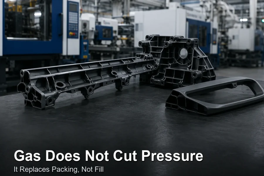
Figure 1: The whole idea in one section — a continuous hollow core, solid skin, and no voids. A void and a channel are different defects; see below.
What Does Gas Actually Save? Work It Out on Your Part
Three numbers decide it: mass removed, clamp tonnage avoided, and cycle time changed. Anything else an article promises is atmosphere.
Mass. A hollow channel removes material from the center of a section, where it contributes least to bending stiffness. For a rib whose thickness is set by a boss or a snap-fit rather than by load, a well-directed channel routinely removes a meaningful fraction of the local mass — and stiffness falls far less than weight, because stiffness tracks the cube of the outer section, which the hollowing barely changes. The corollary is uncomfortable: if your thick section exists only because the designer was afraid of sink, gas is treating a symptom.
Clamp tonnage. Clamping force is projected cavity area times cavity pressure. Conventional packing pressures can reach several tens of MPa at the gate; gas packing sits far below that, so on a large projected-area part the press size is often the single biggest saving. A carrier rail that would need a large machine with conventional packing may run comfortably smaller. That is a real, quotable, monthly-depreciation kind of saving — and it is the strongest business case GAIM has.
Cycle. Cooling is dominated by the thickest section. Hollowing that section thins the remaining wall that has to freeze, so cooling time falls — this is the second genuine win, and it is worth modeling before committing. Our cooling time analysis has the framework.
The arithmetic, with stated assumptions. A 400 mm carrier rail, projected area 600 cm², conventional peak cavity pressure 40 MPa versus gas packing at roughly 5 to 10 MPa. Projected clamp demand scales directly with that figure — which is the difference between two press classes, not a fine-tuning exercise. Substitute your own numbers before you believe ours; the mechanism is the point, not the magnitude.
Internal or External Gas Entry — Which Are You Buying?
Internal means gas enters through a pin that sits inside the melt, giving control over where the channel starts and leaving a small witness mark. External means gas enters at the parting line through an open channel, which is simpler and cheaper and gives away less control.
| Entry | Control over channel | Tool cost | Marks left | Use it when |
|—|—|—|—|—|
| Internal pin | High — you choose the origin | Higher: pin, sealing, servo or valve timing | Small pin mark, needs hiding | Channel route must be dictated, or wall is asymmetric |
| External / parting-line | Low — gas takes whatever is hot | Lower | Parting-line witness along the seal land | Rib runs straight along the parting line, cosmetic class is forgiving |
The decision is almost never “which is better,” it is where the marks are acceptable. Put the pin at the end of the rib on a non-cosmetic face, and design the last 5 mm of the rib as a gas trap where the channel terminates — gas that runs out into an open section loses packing pressure and leaves a sink at exactly the spot everyone looks at.
Figure 2: Injector pins are placed at the rib, not at random. Where they sit is where the channel begins and ends.
What Actually Goes Wrong?
Gas follows heat, so every failure mode is some version of “the gas went where the plastic stayed molten.” That is a thermal problem, not a gas problem.
| Defect | Root mechanism | What to change, in order |
|—|—|—|
| No channel forms | Section too thin, or gas arrived too late after the core froze | Raise melt and mold temperature, inject gas earlier, thicken the section |
| Blow-through / wall puncture | Gas punched through a thin or cold wall into an open area | Move the entry, thicken locally, reduce gas pressure and speed |
| Channel wanders off-axis | Asymmetric wall or a colder side pulling the hot core | Balance wall, even out cooling on both faces |
| Sink at rib end | Gas vented early, no packing held to the end | Extend packing time, add a gas trap at the terminus |
| Internal void, not a channel | Gas arrived after the front froze; shrinkage cavity remains | Earlier gas, hotter melt; check that the vent can release |
| Blisters or fish-eyes after painting | Trapped nitrogen expanding in a later bake cycle | Vent paths, longer packing, lower bake temperature, or abandon GAIM |
| Inconsistent channel part to part | Gas volume or timing drifting; nozzle partially blocked | Log gas mass or pressure-time curve per shot, not pressure only |
The one that hurts most is outgassing. A part that measures fine, weighs right and looks clean can blister in a paint booth two weeks later, because the hollow core contains gas at pressure and a bake cycle expands it. This is why assist-gas parts and painted class-A surfaces are an uncomfortable pair, and why a plating or bonding specification should be stated at quotation stage rather than discovered at PPAP.
Void versus channel is the distinction that settles arguments. A channel is smooth, continuous, follows the thick section and was intended. A void is a rough, isolated shrinkage cavity that formed because the gas arrived too late or the material could not be packed. Both are holes. Only one is a process. Photograph a sectioned part at first article and put the picture in the report, because a dimensional inspection cannot tell them apart.
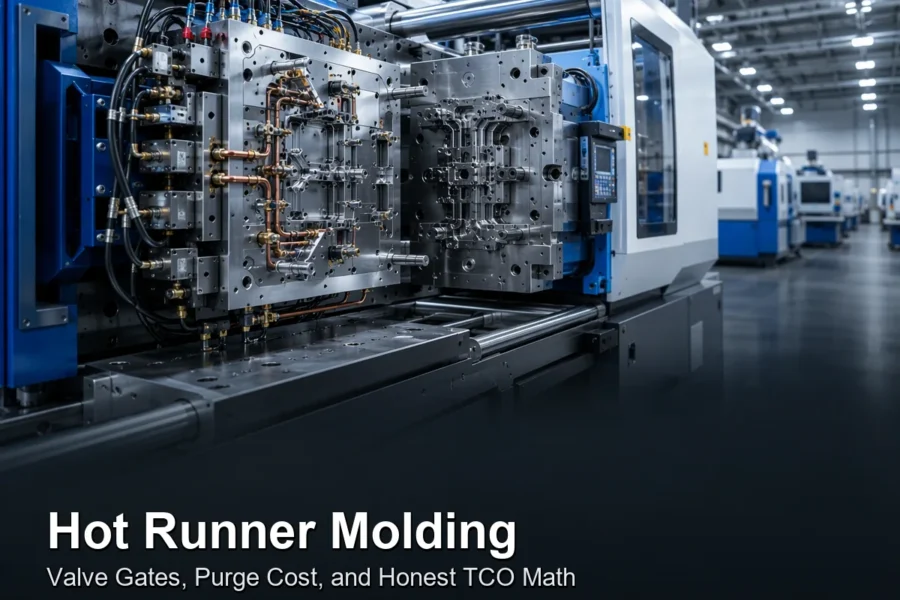
Figure 3: The unit nobody prices honestly. It needs commissioning, a high-pressure supply, and a person who knows what the pressure-time curve should look like.
Which Materials and Parts Suit It?
semi-crystalline and amorphous thermoplastics with a broad melt window do well; glass-filled grades make channel control harder; thin uniform parts do not need it at all.
Good candidates: PA and PP with long rib sections, acrylonitrile butadiene styrene carriers, and glass-filled grades where the rib is genuinely thick. Fiber orientation in glass-filled material does influence how the channel tracks the rib, so expect more sensitivity to injection speed on those grades.
Poor candidates: parts with a uniform wall of 2 to 3 mm, parts where the section is thick but the face is cosmetic class A with no room for a witness mark, and parts destined for solvent bonding or high-temperature coating. If the design already has thick sections sized honestly, the sections that motivate GAIM often disappear on their own.
Resin and mold temperature, gas pressure, gas timing, and the vent path are four interacting controls. If your molder tunes only gas pressure, the process is not characterized.
Case Study: A Carrier Rail That Needed Less Steel, Not More Pressure
Program: 400 mm interior carrier rail, 30% glass-filled PA, rib section nominally 8 mm, projected area about 600 cm². The initial conventional design was rejected for sink on the mounting face and would not fit the press we had.
Client Challenge. The 8 mm rib existed only because the mounting face was sinking. Conventional packing at the required pressure needed a machine with insufficient projected-area margin, and the first three attempts either sank or flashed. Escalated as a machine-size problem. Automotive interior carrier program, 2025, Ideal Pro DFM and tooling records.
Ideal Pro Solution. We did not start with gas. We started with the section. The rib was 8 mm because the local pad around three bosses was 8 mm, so the bosses were cored and reduced to a nominal 60% of the adjoining wall. The rib was then re-proportioned to 6 mm with a gas-directed flow path and a 6 mm gas trap at its terminus, and the internal entry pin was placed on the non-cosmetic end face.
Results and Value. Nominal rib wall from 8 mm to 6 mm with a directed hollow core. Sink on the mounting face eliminated. Projected clamp demand fell enough for the part to run on the available press, so no second machine purchase. Cooling limited cycle reduced by roughly 15% of its previous length once the frozen section thinned. Figures are from our own production records for that program and are specific to that geometry; they are not a prediction for yours.
Transferable Lessons. Gas-assist was the answer only after the section was made honest. Had we added gas to the original 8 mm design, we would have built a channel through a section that never needed to exist and still had a sink problem at the bosses.
Client Quote. “We came asking for a bigger machine. You talked us into changing the rib and it fit the press we already had.”
Figure 4: Same outer shape, same finish, different section. The weight saving is visible only in section, which is why sectioning at first article matters.
When Gas-Assisted Molding Is the Wrong Call
Don’t buy the gas unit for a part whose section can be fixed on the CAD model.
Low volume. Injector pins, a sealed entry, a second control loop and commissioning are fixed costs that a 5,000-piece run cannot carry. If the program is small, low-volume tooling with a properly cored section is the cheaper answer.
Painted or bonded class-A parts. Outgassing risk is not worth the weight saving when a coating line rejects a batch.
Thin or already-hollow parts. If the section is under about 4 mm, there is nothing for the gas to displace. A hollow section inside a hollow section just makes a bad part.
Tight dimensional parts. A gas channel is a mass-distribution decision whose position varies slightly with thermal state. If the feature position is the whole point, do not introduce a second process variable.
Our own honest limits: ISO 9001:2015, RoHS, REACH. We are not IATF 16949 certified. For automotive interior programs we bring process discipline and documentation, not a certificate we do not hold.
Related Reading From Ideal Pro
Gas assist is one decision inside a larger tooling and cost conversation. These cover the parts of it that usually decide a programme before the gas question is even reached.
- Injection mold tooling — how tool cost, steel choice and expected production life interact.
- DFM, defect control and hidden tooling costs — the design-stage checks that remove thick sections before they become a gas-assist requirement.
- H13 hot-work tool steel — the grade usually specified for high-cycle structural parts and the thermal loading that comes with them.
- Injection molding costs — where the fixed cost of a gas system actually lands in a quotation.
- Injection molding process overview — conventional packing, for comparison against the gas-packed sequence described above.
Summary
Gas-assisted injection molding is a way to move material out of the neutral axis of a thick, structural section while holding the skin against the steel — which buys you stiffness per gram, a smaller press, and a shorter cooling phase. It does not reduce the pressure needed to fill the cavity, and the guides claiming that are misreading the process. Its risks are thermal and they are real: blow-through, wandering channels, sinks at rib ends, and outgassing that surfaces in your paint line. Take the decision in the right order — core the pad, fix the bosses, rebalance the wall, and only then ask whether a gas system earns its cost. Send us the drawing with the cosmetic classes marked and we will quote it three ways: conventional, ribbed and cored, and gas-assisted, with the arithmetic shown instead of asserted.
+86 136 5621 3638 ✉ [email protected] ✑ Vraag een offerte aan · Neem contact met ons op
Sources
- Ideal Pro molding and DFM records — assist-gas candidate review, 2023-2026, Huzhou facility.
- Ideal Pro internal tooling data — internal versus external gas entry, injector pin placement and witness marks.
- Ideal Pro DFM checklist — cored bosses and rib proportion guidance.
- Ideal Pro internal material database — resin suitability, gas channel tracking and outgassing observations.
Does gas-assisted molding reduce injection pressure?
No, not the pressure needed to fill the cavity — that still requires normal injection pressure. What the gas replaces is the packing and holding phase, where a screw would otherwise push additional material in. The clamp-tonnage saving is real, the “low pressure” description is not, and confusing the two leads to badly specified tools.
What is the difference between a gas channel and a void?
A channel is a smooth, continuous, intentional hollow that follows the thickest section, formed because gas was injected while the core was still molten. A void is a rough, isolated shrinkage cavity formed because the gas arrived too late or the material could not be packed. Both are empty space; a coordinate measurement cannot tell them apart, which is why sectioned first-article photographs belong in the report.
Can gas-assisted parts be painted or bonded?
With care and sometimes not at all. The hollow core holds gas under pressure, and a bake or cure cycle can expand it and blister the coating from underneath. If your part will be painted, plated or solvent-bonded, say so at quotation so venting, packing and gas volume are designed for it, or the process gets reconsidered.
How much weight can gas-assisted molding save?
It depends entirely on how much of the section sits in the neutral axis, which is why a percentage quoted without your geometry is meaningless. Ask instead for a mass comparison of your part three ways — conventional, cored, and gas-assisted — with the wall geometry shown for each. That comparison is a day of work and it settles the question in a meeting instead of a field failure.
Does it shorten the cycle?
Usually, yes, and this is one of the two genuine reasons to use it. Cooling time is set by the thickest frozen section; hollowing that section thins the wall that has to freeze, so cooling shortens. Model it on your geometry rather than assuming, and check that the added gas step does not eat the gain.
Is gas-assisted molding worth it on a small program?
Rarely. Injector pins, a sealed gas entry, a second control loop and commissioning are fixed costs, and a small volume cannot carry them. On low-volume parts the same weight saving is usually obtained by coring and re-proportioning ribs, which costs nothing but design attention.
Does Ideal Pro do gas-assisted molding?
We evaluate assist-gas candidates and quote them against conventional and cored alternatives, with the trade-offs written down rather than assumed. Send the drawing with cosmetic classes marked and the answer within 24 hours, including the case for not using it.
Over de auteur

Alex Yu
Ideal Pro Manufacturing
Alex is medeoprichter van Ideal Pro, maar wanneer hij niet toezicht houdt op belangrijke projecten of leiding geeft aan het technische team, is hij waarschijnlijk bezig met een lange fietstocht, op zoek naar de beste koffie van de stad, of bezig met het plannen van zijn volgende reisavontuur. Met meer dan 20 jaar ervaring op het gebied van internationale handel en projectmanagement heeft hij het allemaal al meegemaakt: strakke deadlines, lastige technische vraagstukken en alles daartussenin. Hij is ervan overtuigd dat uitstekend werk voortkomt uit een uitgeruste geest en een goede kop koffie, en hij brengt diezelfde nieuwsgierigheid en oog voor detail mee in elk project dat hij aanneemt. Als hij niet op kantoor is, bevindt hij zich meestal ergens in de buitenlucht, waar hij nieuwe plekken verkent en verhalen verzamelt om te delen.
 English
 French
 Dutch
 German
 Japanese
 Korean