 Nederlands



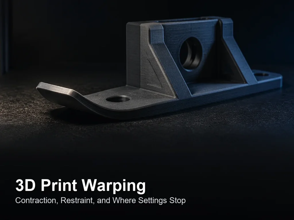
TL;DR — Warping is contraction fighting restraint. The amount of contraction is set by the polymer and the temperature drop, not by your slicer, so a wide footprint on nylon can move more than a whole tolerance band and no setting will recover it. Work the failure in order: how much movement exists, whether the base is holding, then whether the process can even land where your drawing asks.
Key Takeaways
- Contraction is arithmetic. A 200 mm span of a material that shrinks 0.8 percent from processing temperature to room temperature has roughly 1.6 mm of movement to spend before anything restrains it. Most flatness callouts on printed parts are written in tenths.
- A brim, a raft and mouse ears all buy the same thing: bonded area. They add restraint. None of them reduce the force, which is why a brim that lifts at one corner is a brim that was too narrow, not a brim that was the wrong idea.
- Sort failures by when they happen, not how they look. A lift in the first layer is an adhesion problem. A lift after twenty layers is a thermal problem. They photograph almost identically.
- An enclosure is not a universal answer. It raises the temperature of the air around the part, which is exactly what keeps a semi-crystalline part from shrinking early and exactly what pushes an amorphous part toward its heat-deflection limit.
- Flatness is a dimension. If the face matters, put a value and a measurement method on the drawing, and decide whether a printed part can honestly hold it or whether that face should be machined after printing.
Why Trust This Guide
Author: Alex Yu, co-founder of Ideal Pro — 20+ years across mold-making, injection molding and additive manufacturing programmes for customers in 40+ countries. Ideal Pro runs SLA, MJF, SLS, FDM and DMLS capacity alongside tooling and molding, so this page is written from the position of a shop that also has to make the printed part into a production part later.
Method: the process figures used here come from Ideal Pro’s published capability table for its own machines, so every tolerance quoted can be traced to a machine set someone actually owns. Polymer shrinkage ranges are quoted as typical published ranges and must be confirmed against the datasheet for the exact grade you buy, because filled and unreinforced versions of the same resin sit far apart. Arithmetic shown uses stated assumptions so you can substitute your own.
Scope: this covers the mechanism that shows up as a lifted corner, a cupped base or a rocking part. It spans FDM/FFF and touches powder and resin where the restraint problem differs. It does not cover layer adhesion failure, delamination under load or warp in metal powder-bed parts except where the same reasoning applies.
What Is Warping, and How Is It Different From Ordinary Shrinkage?
Set a finished print on a bench and rock it. If one corner drops before the others, that is warping: the part changed shape as it cooled, not merely size. Shrinkage is the uniform part of the story, the one a good printer can design around with a scale factor. Warping is the non-uniform part, and a scale factor cannot fix it because the part did not get smaller in one consistent direction.
Warping is what happens when contraction is unevenly restrained: the polymer wants to shrink, some of it is being held, and the part moves or lifts to relieve the difference.
The distinction matters commercially more than technically. Uniform shrinkage of, say, 0.6 percent can be compensated in the model and survives into the finished part as a slightly smaller but still flat part. Uneven restraint produces the same total movement concentrated at one edge, and that is what puts a mounting face out of flat while every linear dimension on the drawing still measures correctly. A part can pass a caliper inspection and fail the assembly it was made for.
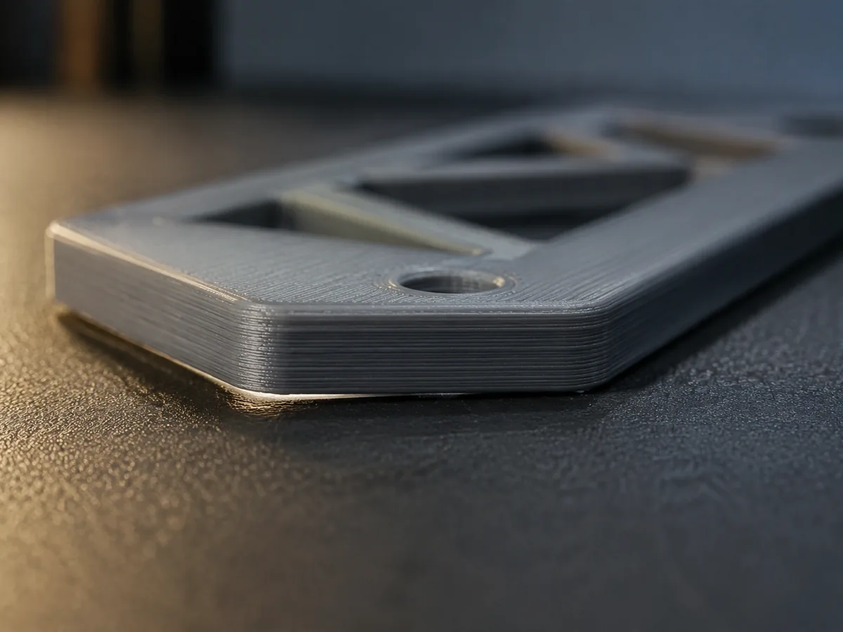
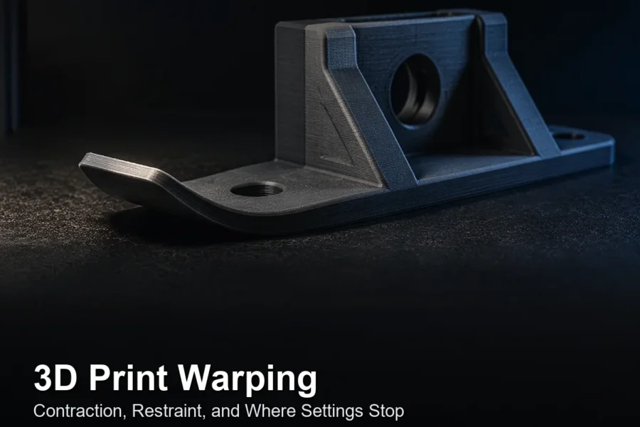
Three shapes cover almost everything you will see on an FDM machine: a corner off the plate, an edge curled along its length, and a base that will not sit flush after removal. They share one mechanism and differ only in where the restraint gave out.
How Much Contraction Am I Actually Dealing With?
This is the question almost every warping article skips, and it is the one that tells you whether you are troubleshooting or negotiating with physics. Take the movement available to the part before anything holds it back:
unrestrained movement ≈ linear shrinkage × span × (1 − fraction restrained)
Typical published in-plane shrinkage on cooling from processing temperature to room temperature runs in these bands. They are order-of-magnitude values for thinking with, not acceptance numbers; your grade’s datasheet outranks this table.
| Material family | Typical published shrinkage | Movement on a 200 mm span | Why it sits there |
|---|---|---|---|
| PLA (amorphous-ish, low crystallinity) | ~0.2 to 0.5 percent | 0.4 to 1.0 mm | Small thermal window between extrusion and set |
| ABS / ASA (amorphous) | ~0.4 to 0.8 percent | 0.8 to 1.6 mm | Wide processing-to-room temperature drop |
| PETG (semi-crystalline tendency) | ~0.3 to 0.8 percent | 0.6 to 1.6 mm | Rate-dependent; crystallises if held warm |
| Nylon PA12 (unfilled) | ~0.7 to 1.5 percent | 1.4 to 3.0 mm | Semi-crystalline, plus moisture uptake after printing |
| Glass-filled nylon | ~0.2 to 0.6 percent across the flow, higher along it | 0.4 to 1.2 mm, strongly anisotropic | Fiber restricts shrink along its length, not across it |
Read the third column before reading any troubleshooting list. If your part is a 200 mm bracket and you call out 0.2 mm of flatness on the base, you are asking the process to suppress most of a movement an order of magnitude larger than the tolerance. That is not a slicer problem. It is a footprint, material or process choice, and it gets decided before the file is sliced.
The second thing nobody writes down is that the anisotropy is often the whole defect. A filled bead shrinks differently along its length than across it, so a wide floor printed in one raster direction develops a gradient through its thickness. The part curls because two layers of the same part disagree about their final size.
The third is time. Nylon keeps moving after it leaves the machine, because it also drinks water from the shop air. Measure a PA part warm and you will sign off geometry that changes by the next morning. Condition parts to the moisture state they will live in, then measure.
Which Fixes Change the Force, and Which Only Add Restraint?
Separate the seven standard interventions into two columns and most confusion disappears. Half the list changes how hard the part pulls; the other half only changes how well the plate holds on. When you treat a restraint fix as a force fix, you get a part that stays down during printing and still comes off out of flat.
| Intervention | What it actually changes | What it costs you | Use it when |
|---|---|---|---|
| Clean plate, correct surface for the material | Restraint: removes the local release point | Minutes per run | One corner fails in the same place every time |
| First-layer squash, Z-offset, levelling | Restraint: makes the bond continuous | A single-layer test patch each step | Gaps between strands, or a glossy translucent bead |
| Heated bed setpoint and soak time | Force: keeps the base above its shrink-trigger while the part is built | Edge flare if you overshoot the range | Base holds for several layers, then lifts |
| Cooling fan speed | Force: controls how fast upper layers contract | Droop, weak bonds, stringing if you go too far | Top edge already curled while the base is fine |
| Enclosure / stable room air | Force: removes directional cooling from drafts | Chamber heat can soften PLA and PETG | Large ABS or ASA part lifting on one side |
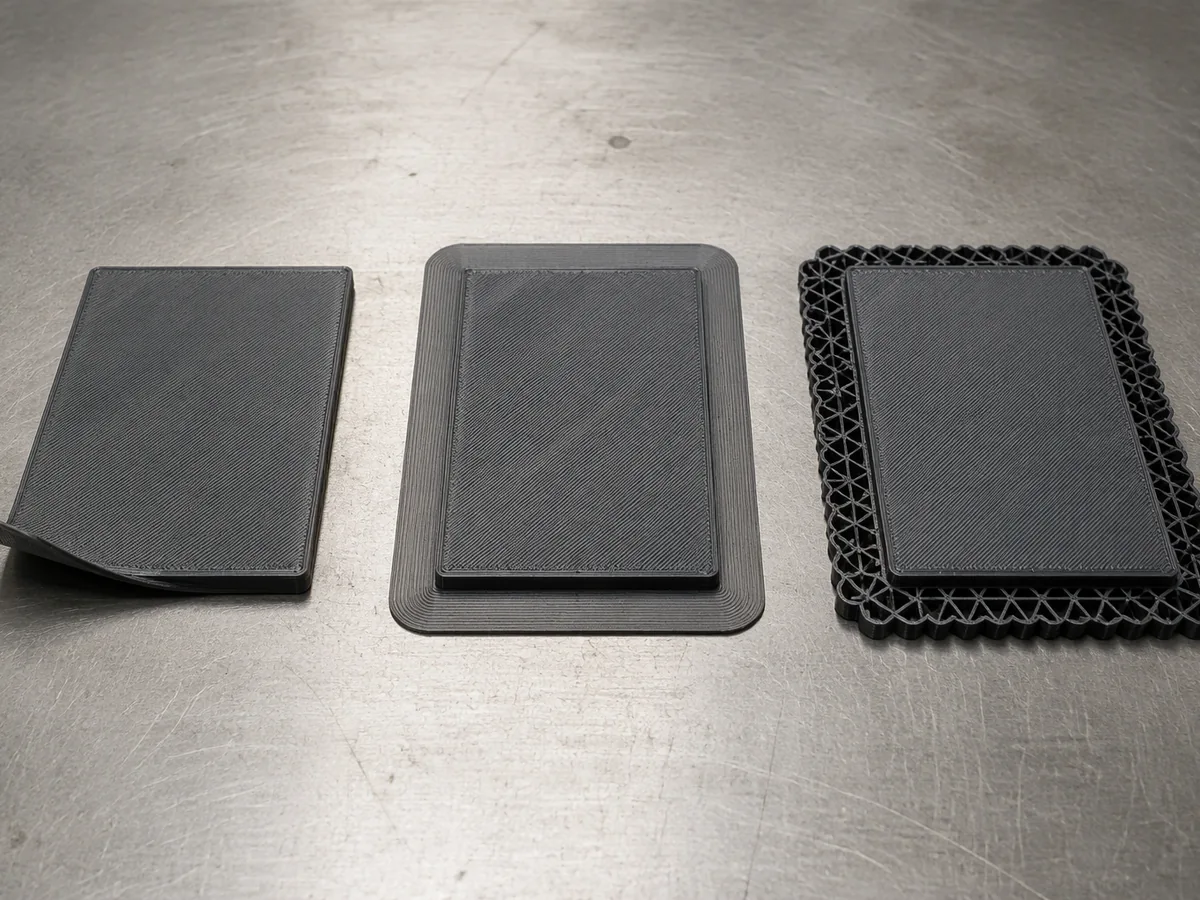
| Brim, raft, mouse ears | Restraint only: more bonded area | Trim time, rougher edge, sometimes a rougher face | Peeling at a known corner while the rest holds |
| Orientation, ribs, corner fillets | Both: shorter spans and less stress concentration | Support marks may land on a functional face | Design is still open; before a third attempt |
The honest limit of brim and raft: bonded area holds a corner down; it does not reduce the contraction stored in the wall above it. Past a point the extra loops only add a trim line, and the part still leaves the plate with the same internal stress, which is why a heavily brimmed part can pass on the machine and then cup after removal once the brim is cut away. You removed the restraint, not the stress.
Should I Change Bed Temperature, Fan Speed, or the Room First?
Triage by timing, not by appearance. The stage at which a part lifts is a narrower signal than any photograph of the lift itself.
| When it lifts | What that rules in | First check | Second check |
|---|---|---|---|
| In the first layer or the first few | Adhesion and nozzle height, not thermal stress | Plate cleanliness and surface choice for the material | Levelling and Z-offset; re-print a single-layer patch |
| After several layers, one corner | Local release point plus accumulating stress | Whether the same corner every run (local) or a random one (thermal gradient) | Bed soak time at setpoint, then a brim on the known corner |
| Late, on the side facing a door or vent | Draft cooling one face faster | Air movement in the room, machine position, HVAC cycle | Enclosure, if the material tolerates a warm chamber |
| Only after removal from the plate | Residual stress released once restraint is cut | Base flatness measured while still on the plate versus after | Geometry: shorter span, ribs, larger corner radii |
| Reproducibly, same file, same machine | The process cannot hold the requirement | Compare movement available against the tolerance called out | Change material, orientation, or the process |
Change one variable per round and confirm with a second run of the same file. One part that stayed down can be a plate that happened to be warm. Three settings moved together give you one result and three suspects, which is how a two-hour print becomes a two-week argument with your own machine.
What Does an Enclosure Really Do, and When Does It Backfire?
An enclosure does one useful thing: it stops one side of the part cooling faster than the other, and it keeps the surrounding air warm enough that the base does not contract while the top is still soft. For ABS, ASA and nylon that is usually decisive on anything bigger than a small block.
It also does one damaging thing, and the same guides rarely mention it. A chamber raises the temperature the part sits at for the whole build. Every amorphous material softens as it approaches its heat-deflection range, so a PLA or PETG part in a hot chamber can slump in its upper layers, lose overhang definition, or simply sag somewhere between layer 200 and layer 300. You traded corner lift for a different defect and moved it to a face you care about.
The practical rule: enclose the materials with a wide processing-to-room temperature drop and a high glass-transition temperature, and ventilate the ones that do not need it. If you must run PLA on a large footprint, address the footprint instead — see the geometry section below.
How Do I Design the Part So It Has Less to Lose?
Most warping arguments are settled before slicing, by three decisions.
Shorten the span that has to stay flat. Movement scales with span, so a 300 mm floor collects roughly 1.5 times what a 200 mm floor does at the same shrinkage. A rib or a shallow groove partitions a wide floor into narrower strips that each have less movement to spend, which is the same trick wall-thickness and rib design uses in molding for exactly the same reason.
Remove the stress concentrator. A sharp inside corner is where the least material meets the highest gradient. A fillet spreads the load. On printed parts this is also a fatigue story, so the radius earns its place twice.
Choose orientation against the datum, not against the supports. Flat on the plate, the whole length is pinned and the far end lifts. On its side, one narrow edge carries the grip and the stair-step lands on a face you may need. Decide which face another part locates against, put the least movement on that face, and accept the support marks somewhere the drawing does not care about. If a face needs both orientation-driven quality and a specific finish, that is a post-processing decision and it should be made in the quote stage rather than discovered at removal time.
How Should Flatness on a Printed Part Be Specified and Inspected?
This is where most printed parts quietly fail: nobody said what “flat” meant, so the supplier applied its own default and the buyer lost the right to reject on that feature.
Three things have to be on the drawing:
- Which face. Name the datum face, and show it on the model.
- What value, over what area. Flatness applies to a surface, not to a length; state whether the value covers the whole face or a defined zone.
- When it is measured. Before or after finishing, and at what condition for hygroscopic materials such as nylon.
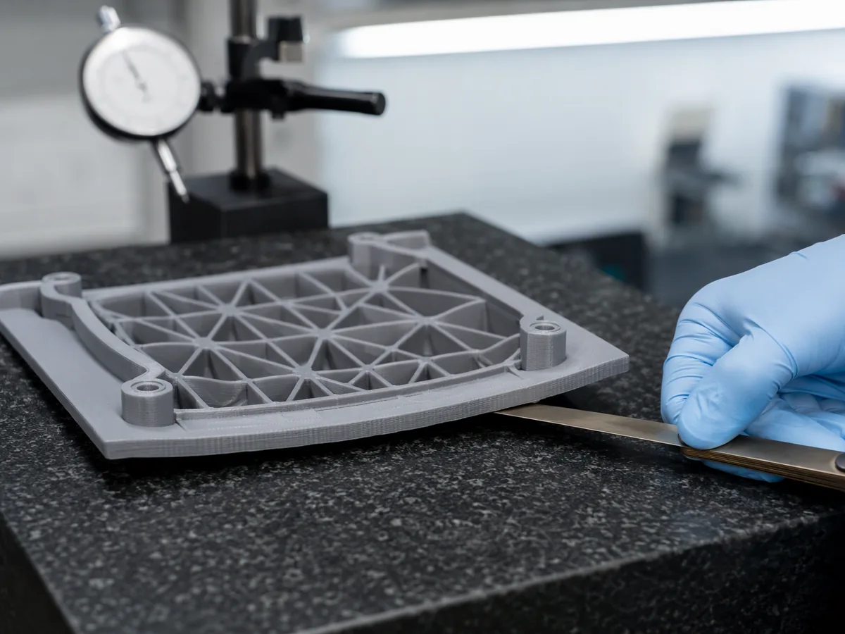
Then agree the method, because a surface-plate feeler check and a CMM best-fit plane do not return the same number on the same part. A best-fit plane can hide a lifted corner inside a plane that averages it away. Ask for the measurement to be taken against the datum you named, and ask whether the report ships with the parts — the same question you would ask on a tool try-out or a production inspection.
And measure at room temperature after the part has sat. A base checked warm reads flatter than it will look the next morning, which is not a defect in the print but a defect in the acceptance check.
When Is a Warped Print Acceptable, and When Must It Be Reprinted?
The same lift gets three different answers, and the difference is what the distorted face has to do.
- Accept when the face seals against a compressible gasket, the fasteners still line up, and the part sits without rocking. Cosmetic covers tolerate a small lift on a non-mating edge.
- Accept with conditions when the face is visible but not load-bearing, and the lift is inside the value on the drawing. Write it down; an undocumented acceptance becomes a dispute later.
- Reprint when the distortion reaches a surface another part locates against, changes a controlled geometry, or affects a load path that cannot be verified after any repair. Controlled reheating can flatten a mild lift, but the part may distort again, lose strength, or drift out of dimension within days.
An enclosure base with a cupped floor still closes if the gasket compresses enough. A mounting bracket with the identical cup tilts everything bolted to it. A locating fixture with the same cup puts every part it holds out of position. Which one you are holding decides whether 0.3 mm matters, not the number itself.
Why Won’t Printing Hold a Flat Mounting Face — and What Do I Do Then?
Because on a wide footprint the movement available to the polymer is usually larger than the flatness anyone wants. Once you have cleaned the plate, corrected the first layer, soaked the bed, tamed the fan, enclosed the machine and added a brim, the remaining error is not a setting. It is the process envelope.
At that point there are three honest routes, and a printing-only supplier has an incentive to talk you out of two of them.
| Route | When it wins | What it costs |
|---|---|---|
| Print, then machine the critical face | One or two faces must be truly flat and everything else can stay printed | A second operation and a fixturing decision; the fine detail must be sequenced after machining so the clamp does not crush it |
| Change the additive process | The restraint problem is footprint-driven and a powder or resin process cools more evenly at your size | Material and cost envelope change; check minimum wall and tolerance per process |
| Move the part off printing | You need the same flat face in tens or thousands of pieces, repeatably | Tooling and lead time; see the cost crossover arithmetic |
Machining the datum is often the cheapest real fix and the least discussed one. A printed fixture body with a milled mounting face gives you the geometry freedom of additive and a surface a dial indicator stops arguing with. That is precisely why a shop that runs CNC capacity and printing under one roof can offer it, and why a quote should ask which faces have to be machined rather than assuming the print is the last operation.
When the volume climbs, the crossover is not a matter of taste. Vacuum casting bridges tens of parts with a moulded surface quality, and low-volume molding holds a flat face because a steel parting line does it every cycle instead of asking a layer process to do it once. Price the same flatness callout all three ways against one delivery date; a print quote and a tooling quote rarely inspect the same dimension, and that difference is where the surprise lives.
There is also the reverse trap: a printed part that succeeds and then cannot be molded. Walls thinner than a molding process will take, undercuts that no longer have a draw direction, and textures that will not release all print beautifully and fail at the tool. If the print is a stand-in for a molded part, review it against molding limits now rather than after the prototype is signed off — see tooling design and our warpage analysis for thin-wall molding, where the same contraction logic shows up with different levers.
Does Moisture Have Anything to Do With My Corner Lifting?
More than the troubleshooting lists admit. Nylon, PETG and TPU take up water from shop air, and that water does two things to a print that is already fighting contraction.
First, it changes the material you are printing. Wet filament pops steam at the nozzle, leaves splay and a rougher surface, and — less visible — shifts the temperature at which the bead sets. A rougher first layer bonds differently, which is how a moisture problem arrives disguised as an adhesion problem.
Second, it changes the part after printing. A dried nylon part and a conditioned nylon part are not the same size. If you print dry, measure dry, and ship to a humid climate, the face you accepted can move after acceptance. This is the identical reasoning behind drying discipline in molding, where a hopper that is behind schedule shows up as splay and dimensional drift in the same batch.
Treat it as a prerequisite rather than a tip. Dry the material to the grade’s recommendation, print it, and state on the drawing the moisture condition at which dimensions are verified.
What Does a Warped Attempt Actually Cost Me?
Count the whole round, not the filament. A failed 300 mm print at six hours of machine time costs the machine hours, the material in the part and its brim, the removal and cleanup time, the person who was watching it, and — usually the largest item — the days around it while the next attempt is queued.
Compare that with a quote. A third attempt costs material, machine hours and the calendar around both. A manufacturability review costs one engineering pass and answers a question your slicer cannot: whether the flatness you want is inside the envelope of the process you chose. This is the same decision-latency problem we see on tooling programmes, where the binding constraint is almost never the machine and almost always the time between seeing a problem and having someone qualified look at it.
Practical threshold: if two attempts on the same file have lifted the same feature, a third attempt with one more setting changed is usually buying information you can get faster from a DFM review — especially when the alternative is machining that face or moving it to a moulded process. Send the file with the failed orientation and a photograph; that combination rules out half the hypotheses before anyone opens a slicer.
Related Reading From Ideal Pro
- SLA, MJF, SLS and FDM capability, materials and tolerance table — the per-process minimum wall, layer height, build size and tolerance figures used in this article.
- Warpage analysis in thin-wall injection molding — the same contraction-versus-restraint problem with tool-side levers.
- What affects thermoplastic shrinkage — why a grade’s shrinkage is a range, not a number.
- Eliminating sink marks — the localised sibling of warping when the wall is thick rather than the span wide.
- CNC machining services — when printing the body and milling the datum is cheaper than a fourth attempt.
Summary
Warping is contraction against restraint, and the quantity of contraction comes from the polymer and the temperature drop rather than from your slicer. Work it in order: estimate the movement available on your span, confirm the base is holding for the right reason, control the direction of cooling, then design the span and the corners so the part has less to lose. Brim, raft and mouse ears buy bonded area, not lower stress, which is why a part can stay down and still come off cupped.
Then decide what the face has to do. Put a flatness value and a measurement method on the drawing, condition hygroscopic materials before you accept anything, and when the movement available is bigger than the tolerance you want, stop tuning: machine that face, change the process, or move the part to a route that holds it every cycle.
Sources
- Ideal Pro 3D printing capability table — per-process minimum wall, layer height, maximum build size, dimensional tolerance and lead time, at /3d-printing/. All Ideal Pro figures quoted here come from that table.
- The technical data sheet for the exact resin grade you purchase. Shrinkage ranges in this article are typical published bands for the family, not acceptance values; the grade sheet outranks them.
- ISO 1101 for the definition and callout of flatness as a geometrical tolerance, and the tolerance standard named on your drawing for general limits.
+86 156 0682 1288 (Tel/WhatsApp) ✉ [email protected] 🌐 Request a quote
Veelgestelde vragen
Is 30 percent regrind too much to blame my warping on?
Regrind is not the first suspect on a printed part, because FDM has no sprue to reprocess. What transfers is the principle: each thermal history changes the material. If your filament was dried, printed, then stored open, you have already given it two histories before the print starts, and a cupped base is one of the ways that shows.
Why does my part lift at the same corner every single time?
Because that corner has a local cause, not a thermal one. Reproducibility is a diagnostic gift: look at plate cleanliness at that spot, a chip in the surface coating, a levelling error at that XY position, or a nozzle gap that opens as the bed flexes under the gantry. Fix the local restraint before you touch temperatures.
Does a brim reduce warping or just hide it?
It adds bonded area, which is restraint. It genuinely prevents the lift during printing, and if the part must stay flat as printed, that is a real win. It does not lower the stress locked into the wall above, so once you cut the brim off, a part with a lot of movement available can still cup. Judge the part after the brim is removed, in the state you will use it.
Can I flatten a warped print with a heat gun?
You can often reduce a mild lift with controlled reheating, and you should treat it as a trial rather than a repair. The part can distort again within days, lose strength where you over-heated a layer bond, or drift out of a dimension your drawing controls. On a functional face, the honest comparison is usually reheat versus reprint versus machine that face.
Which process warps less, SLS or FDM?
Ask instead which one puts less unrestrained span into a hot, gradient field. A powder process builds inside a warm bed with the unfused powder supporting the part, which removes the peel-at-a-corner failure mode entirely, at the cost of its own shrinkage and its own minimum wall. Ideal Pro's published figures put minimum unsupported wall at 0.7 mm for PA12 SLS against 0.8 mm for FDM, with tolerance ±0.3 mm on SLS against ±0.2 mm on FDM for parts over 100 mm, so the exchange is not free in either direction.
Should I put flatness on the drawing or leave it to the printer?
Name the face, give the value, and say whether it applies before or after finishing. A callout tighter than the process holds means a secondary operation, and that decision belongs before the file is quoted. If you write nothing, the supplier applies its default and you lose the argument afterwards.
Does Ideal Pro hold flatness on printed parts?
Inside the envelope of the process you choose, yes, and it is measurable: our published dimensional tolerance by process is ±0.2 mm on SLA, MJF and FDM and ±0.3 mm on SLS, with the percentage adder for spans beyond 100 mm. Where a face needs better than a layer process can hold, we machine it after printing rather than promising the print will get there. Send the drawing with the datum face marked and we will quote the flatness and the route together.
Over de auteur

Alex Yu
Ideal Pro Manufacturing
Alex is medeoprichter van Ideal Pro, maar wanneer hij niet toezicht houdt op belangrijke projecten of leiding geeft aan het technische team, is hij waarschijnlijk bezig met een lange fietstocht, op zoek naar de beste koffie van de stad, of bezig met het plannen van zijn volgende reisavontuur. Met meer dan 20 jaar ervaring op het gebied van internationale handel en projectmanagement heeft hij het allemaal al meegemaakt: strakke deadlines, lastige technische vraagstukken en alles daartussenin. Hij is ervan overtuigd dat uitstekend werk voortkomt uit een uitgeruste geest en een goede kop koffie, en hij brengt diezelfde nieuwsgierigheid en oog voor detail mee in elk project dat hij aanneemt. Als hij niet op kantoor is, bevindt hij zich meestal ergens in de buitenlucht, waar hij nieuwe plekken verkent en verhalen verzamelt om te delen.


 English
 French
 Dutch
 German
 Japanese
 Korean