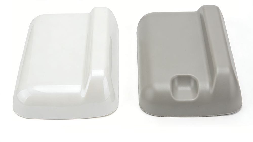
Surface sink marks (also known as shrinkage voids) are depressions that appear on the surface of a molded part. They are caused by the volumetric shrinkage of the plastic during the cooling phase. Because plastic has poor thermal conductivity, the cooling process is complex, making these defects difficult to eliminate completely.
Generally, thicker sections cool slower than thin sections, leading to shrinkage. Additionally, if the mold has local temperature variances, the hotter areas will cool slower and are more prone to sink marks.
Design Tip: To prevent sink marks, design parts with uniform wall thickness. Make ribs and bosses thinner, add fillets (round corners), or use surface textures (grain/matte) to visually hide minor shrinkage.
Here is a detailed analysis of the 7 main factors causing sink marks and how to solve them.
Insufficient Compression (Packing)
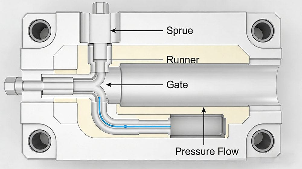
If the runner system (sprue, runner, and gate) is smaller in volume compared to the thick part wall, injection pressure cannot be effectively transmitted to the melt in the cavity. This results in increased shrinkage and larger sink marks.
Key Issues:
- Small Gates: If the gate is too small, it freezes off (solidifies) before the part cools. Even with sufficient holding time, pressure cannot reach the melt, causing shrinkage. This is common in crystalline plastics (like PP, PA) which have distinct melting points.
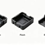
- Mold Flash: If the mold clamping force is insufficient and the mold opens slightly (flashing), pressure is lost, leading to sink marks.
- Machine Type: Screw-type injection molding machines use a check ring (non-return valve). While this prevents backflow, it can sometimes lead to more sink marks compared to plunger-type machines if not calibrated correctly.
✅ Solutions:
- Increase Gate Size: Enlarging the gate diameter is highly effective.
- Increase Pressure: Boost injection pressure and holding pressure.
Gate Location: Place the gate near the thickest section of the part. If sink marks appear far from the gate, it is due to pressure loss over the flow path.

Improper Injection Volume Adjustment
For screw-type injection molding machines, you must leave a cushion of molten plastic between the screw head and the nozzle at the end of the injection phase.
The Problem: If the injection volume is set so that the screw bottoms out (hits the limit) exactly when the cavity is full, the cushion becomes zero. The screw cannot move forward to apply holding pressure. Consequently, the plastic shrinks without compensation, creating sink marks.
✅ Solution: Ensure a buffer (cushion) remains. At the end of injection, the screw should still be able to advance a few millimeters (typically 3-5mm depending on machine size) to maintain pressure.
Sink Marks on Working Surfaces
Sometimes, internal shrinkage is acceptable, but surface sink marks on the "A-side" (appearance side) are not.
The Logic: The side of the part touching the hotter mold surface will cool slower and is more likely to show sink marks. The cooler side solidifies faster and resists pulling in.
✅ Solution:
- Cooling Control: Intensely cool the side where sink marks are not allowed.
- Temperature Differential: Conversely, heat the side where sink marks are permitted (the non-appearance side) to draw the shrinkage to that area.
Uneven Cooling (Wall Thickness Variation)
When a part has uneven wall thickness, the thick sections cool much slower than the thin sections, causing sink marks in the thick areas.
✅ Design Solutions:
- Uniformity: Keep wall thickness as consistent as possible.
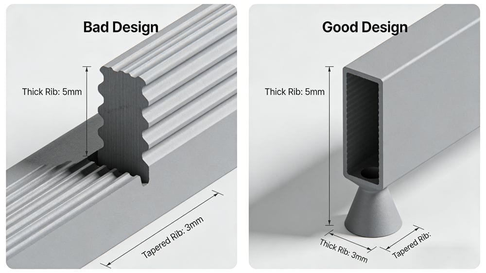
- Coring Out: If a boss (cylindrical protrusion) must be thick, hollow out the center (core it out) to reduce mass.
- Reinforcement: Instead of thickening a boss for strength, use ribs.
✅ Process Solution: If precision is not critical, you can eject the part while the core is still soft (but the skin is solid) and let it cool in air or warm water. This creates a gradual, less visible depression rather than a sharp defect.
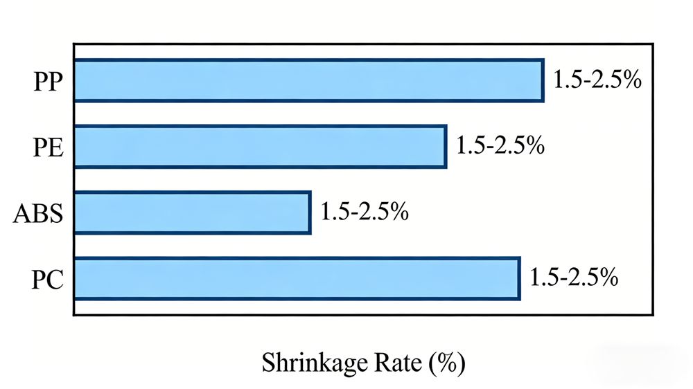
Excessive Shrinkage Rate (Material Selection)
The thermal expansion coefficient of the plastic itself is a major factor.
Material Comparison:
- PE (Polyethylene): Shrinkage ~2.0% - 5.0% (High risk)
- PP (Polypropylene): Shrinkage ~1.0% - 2.0% (High risk)
- PS (Polystyrene): Shrinkage ~0.2% - 0.6% (Lower risk)
Crystalline plastics (PP, HDPE, POM) have a significant density difference between their solid and molten states, making sink marks very difficult to prevent.
✅ Solutions:
- Material Change: Switch to an amorphous copolymer (like ABS or PC) which shrinks less.
- Fillers: Use plastics filled with inorganic materials like Glass Fiber or Talc. These fillers reduce the overall shrinkage rate.
- Verwerking: Lowering the melt temperature can help, provided the pressure is high enough to fill the mold.
Slow Surface Solidification
Sink marks in thick areas occur because the surface layer hasn't formed a strong "skin" before the center shrinks. The shrinking core pulls the soft surface inward.
✅ Solutions:
- Thicken the Skin: Lower the mold temperature and melt temperature. This helps the surface solidify faster, forcing the shrinkage to become an internal vacuum void (bubble) rather than a surface dent.
- Flow Speed: Reduce the speed of the melt as it passes through thick sections.
- Additives: Adding a foaming agent can sometimes compensate for shrinkage.
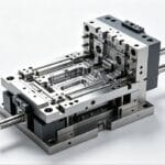
Mold Design Adjustments
If process adjustments fail, the mold geometry may need modification.
Modifications:
- Add Overflow Wells: Add a "flash land" or overflow tab at the location of the sink mark to draw the shrinkage away from the cosmetic surface (See Fig A concept).
- Widen Flow Paths: If the material path to a thick area is narrow, widen it to ensure pressure reaches that spot (See Fig B concept).
- Rib Design: Avoid large thickness differences. Make ribs shorter or use a "dog-bone" design to reduce mass at the intersection (See Fig C concept).
Summary: Troubleshooting Matrix
| Factor | Potential Cause | Quick Fix |
|---|---|---|
| Machine | No cushion / Screw bottoms out | Adjust shot size to leave buffer |
| Proces | Low Holding Pressure | Increase Holding Pressure & Time |
| Mold | Gate too small or frozen | Enlarge gate diameter |
| Materiaal | High Shrinkage (e.g., PP) | Switch to Glass-Filled grade |
| Ontwerp | Thick walls / Ribs | Core out thick sections |
Hope this guide helps you solve your injection molding quality issues! Don't forget to share this post with your manufacturing team.