Mastering Injection Molding Speed Segmentation: The Ultimate Guide
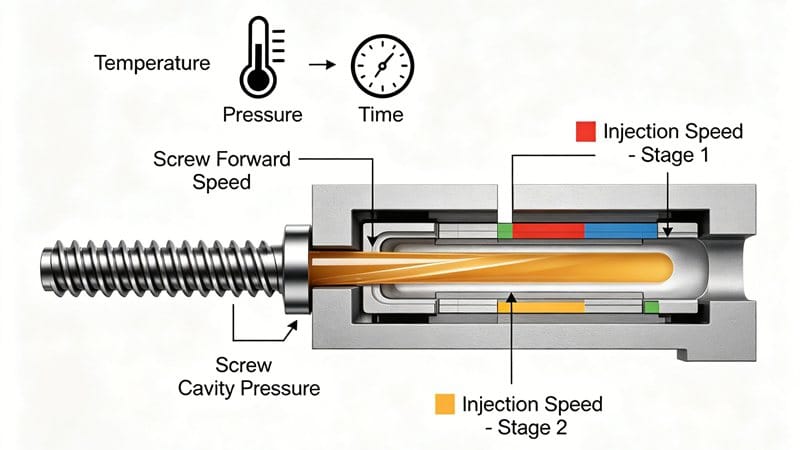
射出成形1 is a complex dance of temperature, pressure, and time. Among these, injection speed (ram speed)2 plays a pivotal role in determining the quality of the final part.
Why is speed segmentation so critical? Because the velocity of the melt front directly affects molecular orientation and internal stress. To achieve a stable melt surface speed and minimize defects, you cannot rely on a single speed setting. You must master speed segmentation.
In this guide, we will explore the golden rules of speed profiling and how to adjust them for different geometries and materials.
💡 Pro Tip: Since melt flow velocity3 is difficult to measure directly, we often calculate it indirectly by measuring the screw forward speed or cavity pressure (assuming the non-return valve is leak-free).
The Golden Rules of Speed Segmentation
To ensure a smooth transition from one set point to another and maintain a constant fluid surface speed, we recommend adhering to the following principles:
- Constant Surface Speed: The velocity of the melt front should ideally remain constant.
- Prevent Freezing: Use rapid injection to prevent the melt from freezing prematurely during the filling process.
- Critical Areas: Balance the need for rapid filling in runners with reduced speed at the gate (entry point).
- Stop Immediately: Ensure the injection stops the moment the cavity is filled to prevent over-packing, flash, and residual stress.
- Geometry Matters: Settings must account for mold geometry, flow restrictions, and instability factors.
Material & Geometry Considerations
Material characteristics are paramount. Polymers can degrade due to excessive stress. While higher melt temperatures can lead to oxidation, they also reduce viscosity and shear stress.
Speed segmentation is particularly helpful for heat-sensitive materials4 such as PC (Polycarbonate), POM (Acetal), and UPVC.
Mold Geometry Guidelines
| Geometry Feature | Recommended Speed Strategy | Reason |
|---|---|---|
| Thin Walls | Maximum Injection Speed | To fill the cavity before the material freezes. |
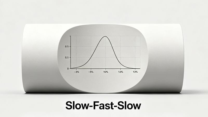
| Thick Walls | Slow - Fast - Slow Profile | To avoid surface defects and sink marks. |
| Cross-Sections | Decelerate | When the melt front reaches a cross-sectional area change. |
| Long Runners | Fast Fill | To reduce cooling of the melt front (except for high viscosity materials like PC). |
| Radial Diffusion | Balanced Increase | Ensure the melt volume increases evenly. |
Troubleshooting Defects via Speed Control
Most injection molding defects can be solved by adjusting the injection speed. Here is how to tackle common issues.
1. Gate Defects (Burn Marks & Flow Lines)
When melt passes through a gate, the surface may cool or stagnate. If the speed is too high, excessive shear creates pressure peaks, leading to gate burns または flow lines.
- The Fix: Decelerate just before the gate to prevent excessive shear, then accelerate once through.
- 注: Precise control at the gate is difficult; decelerating at the end of the runner is often a more practical solution.
2. Flash & Air Traps (End of Fill)
Over-packing causes flash (excess material escaping the mold), while poor venting causes air traps.
- The Fix: Use a slow speed in the final segment of injection. This prevents over-filling and allows air to escape through vents, reducing residual stress.
3. Short Shots
If the speed is too slow at the gate or if the melt freezes locally, you get a short shot (incomplete part).
- The Fix: Increase injection speed immediately after passing the gate or local flow obstructions.
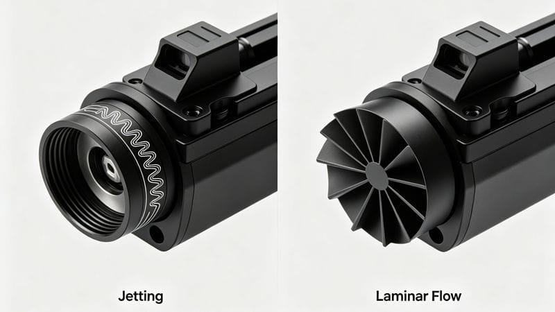
4. Jetting (Snake-like Streams)
Jetting occurs when the melt shoots through the gate without attaching to the mold walls. This is common with low viscosity materials or high barrel temperatures.
- The Fix: The key is finding the transition point. You must fill the runner quickly, then slow down significantly as you pass through the gate. If you switch too late, inertia causes jetting.
Summary: Speed Adjustments for Common Defects
Use this table as a quick reference for your process optimization.
| Defect Type | Primary Cause | Speed Adjustment Strategy |
|---|---|---|
| Short Shot | Flow hesitation / Freezing | Increase Speed at gate/obstruction. |
| Flash | Over-packing | Decrease Speed in the final stage. |
| Burn Marks | Trapped air / High Shear | Decrease Speed at gate; Slow down end of fill. |
| Jetting | High Inertia at gate | Slow down immediately after gate entry. |
| Sink Marks | Low Pressure Transfer | Increase Speed to maintain heat/pressure. |
| Wavy Lines | Viscosity changes | Optimize speed to ensure stable flow front. |
結論
Smooth parts depend on injection speed. Whether you are working with glass-fiber-filled materials (which are sensitive to shear) or heat-sensitive polymers, the logic remains the same: maintain a stable melt front velocity.
By understanding the relationship between geometry, material viscosity, and injection speed, you can eliminate defects like short shots5, flash, and burns. Mastering speed segmentation is not just a setting—it is the art of injection molding.
Explore cutting-edge advancements in injection molding to enhance your production efficiency and part quality. ↩
Understanding injection speed is crucial for optimizing the quality of molded parts. ↩
Learn about the methods to measure melt flow velocity for better process control. ↩
Explore the challenges and strategies for working with heat-sensitive materials. ↩
Learn how to identify and fix short shots for better production outcomes. ↩