

Why Do Flow Mark Defects Happen in Injection Molding?
Do wavy lines ruin the look of your Injection Molding parts? These ugly marks cause high scrap rates. We will show you how to fix and prevent this costly defect.
Flow marks are wavy, ring-like surface defects on injection-molded parts. They happen when plastic melt cools too fast or flows unevenly in the mold cavity. Fixing them requires adjusting injection speed, increasing mold temperature, and improving gate design for a smooth, consistent fill.
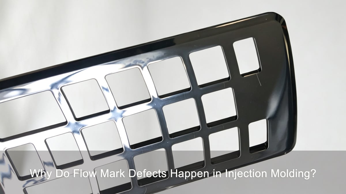
Let us break down exactly what causes these wavy patterns and how our engineering team at Ideal Pro solves them. You can save time and money by learning to spot the root causes early.
Why Do Flow Marks Hurt Your Plastic Part Quality?
Customers hate parts with bad surface finishes. If you ignore flow marks, you lose trust. Let us look at why these cosmetic flaws mean deeper structural trouble.
Flow marks indicate unstable melt-front behavior. They show that plastic layers cooled at different rates inside the mold. This leads to poor surface quality, weak fusion points, dimensional shifts, and higher scrap rates in mass production.
At Ideal Pro, we tell our clients that a flow mark is not just an ugly wavy streak. It is a clear warning sign. When you see flow marks, the plastic melt did not flow smoothly inside the cavity.
Hidden Structural Problems
When the plastic cools at different speeds, it creates stress inside the part. This internal stress makes the part weak. If you drop the part, it might break right where the flow mark is. The plastic layers simply did not bond together properly. We always look beyond the surface to protect the strength of your product.
Production and Cost Issues
Bad parts go straight into the trash. This raises your scrap rate. A high scrap rate means you waste money and time. Our mission is "Sustainable Solutions, Enduring Excellence." We do not just hide the mark. We fix the process so you save money over the long term. We want your production to run perfectly every single day.
| Issue Type | Direct Impact | Long-Term Result |
|---|---|---|
| Cosmetic | Bad surface finish | Customer rejects the part |
| Structural | Weak fusion points | Part breaks during regular use |
| Dimensional | Uneven shrinking | Parts do not fit together properly |
What Are Flow Marks and Where Do They Typically Appear?
Are you unsure what a flow mark looks like? Identifying the defect wrong leads to wasted time. Here is how to spot them correctly.
Flow marks look like wavy, circular bands or ripples on the part surface. They usually appear near the gate, at thin wall sections, or at the end of the flow path where the plastic melt starts to cool and slow down.
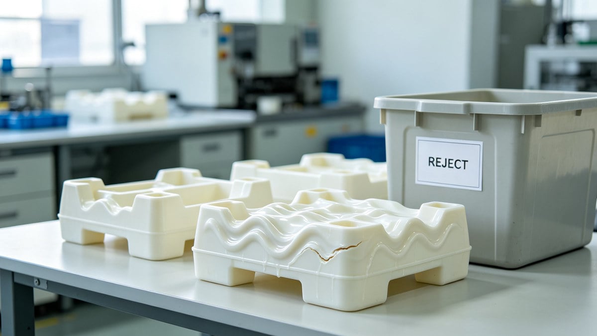
You need to know exactly what you are looking for. Flow marks often look like the rings on a tree stump or ripples in a pond. They are very easy to see under a bright light.
Visual Cues of Flow Marks
The marks form a pattern of lines. These lines sit perpendicular to the direction of the plastic flow. If the plastic flows straight down a tube, the rings wrap around the tube. The color of the mark often looks slightly duller than the rest of the shiny plastic.
Common Trouble Spots
We often find these marks in specific areas of the mold. The gate area is the most common spot. This is where the plastic enters the cavity. If the gate is too small, the plastic struggles to get through smoothly. We also see them in very thin walls. The plastic cools too fast in thin areas. Finally, they show up at the very end of the part where the plastic loses all its heat and pressure.
| Defect Location | Why It Happens Here | Visual Pattern |
|---|---|---|
| Near the Gate | Sudden pressure change | Concentric rings |
| Thin Walls | Very fast cooling | Wavy lines |
| End of Flow | Low pressure and low heat | Faint ripples |
How Do Flow Marks Differ from Jetting, Weld Lines, and Splay?
Mixing up flow marks with other defects is a huge mistake. You will change the wrong machine settings. Let us clear up the confusion.
Flow marks form wavy rings near the gate. Jetting looks like a snake pattern. Weld lines are straight lines where two flows meet. Splay shows silver streaks from moisture. Knowing the difference stops endless trial-and-error during production.
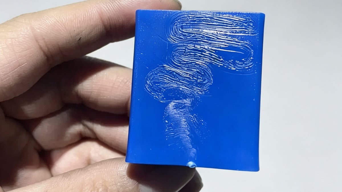
Misdiagnosing flow marks as jetting or weld lines often causes endless trial-and-error on the factory floor. I see operators adjust the wrong settings all the time. This wastes hours of machine time and expensive plastic.
Stop the Guesswork
If you think a flow mark is splay, you might waste hours drying the plastic more. But drying the plastic will not fix a flow mark. You must look closely at the shape of the defect. We train our team to use magnifying glasses to inspect the surface.
Key Differences
Jetting happens when plastic shoots into an empty space too fast. It folds over itself like a snake. Learn more about jetting marks and how to fix them. A weld line is a single crack-like line. It happens when two separate plastic flows crash into each other. Splay looks like tiny silver bubbles popping on the surface — see our guide on eliminating silver streaks and splay marks for details. Flow marks are just gentle ripples in one single flow direction.
| Defect Name | Visual Appearance | Primary Cause |
|---|---|---|
| Flow Mark | Wavy rings, gentle ripples | Uneven cooling, slow speed |
| Jetting | Snake-like ribbon pattern | Injection speed too high at gate |
| Weld Line | Single thin straight line | Two melt fronts crashing together |
| Splay | Silver streaks or splashes | Wet raw material |
How Do Flow Marks Form During Melt Filling?
Do you wonder what happens inside the mold? Guessing the melt behavior causes bad mold designs. We need to look at the core mechanism.
Flow marks happen when the plastic melt front slows down and cools too quickly. The outer layer freezes against the mold wall, while fresh hot plastic pushes past it. This uneven cooling and rolling effect creates a wavy pattern on the surface.
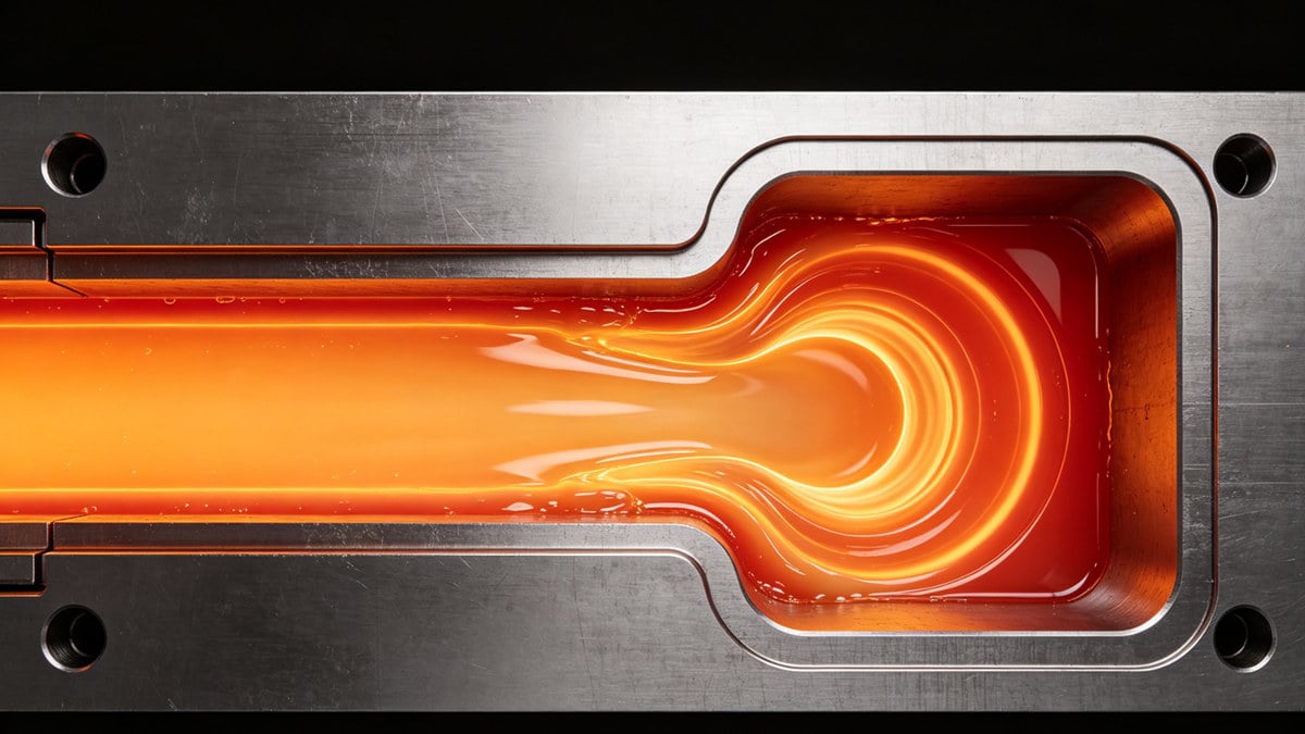
To stop flow marks, you must understand how plastic moves. We call this movement melt-front behavior. It is the secret to perfect injection molding.
The Fountain Flow Effect
Plastic does not flow like water. It flows more like thick syrup. The plastic in the middle of the stream moves faster than the plastic touching the cold mold walls. The hot plastic in the center pushes forward and rolls outward to the walls. We call this fountain flow. When fountain flow is stable, the part looks perfect.
When the Process Fails
If the mold is too cold, the plastic touching the wall freezes instantly. The hot plastic behind it has to push much harder to get past the frozen layer. It stutters and jumps. This stuttering creates the wavy rings you see on the finished part. The melt front basically stops and starts over and over again.
| Flow Aspect | Ideal Condition | Defect Condition |
|---|---|---|
| Melt Front | Smooth and steady | Stuttering and jumping |
| Cooling Rate | Gradual and even | Sudden and uneven |
| Wall Contact | Rolls smoothly outward | Freezes too fast on metal |
What Are the Major Root Causes of Injection Molding Flow Marks?
Fixing defects blindly wastes expensive raw material. You must know the exact triggers. Here are the main reasons these wavy lines appear.
Unstable actual melt temperature, poorly tuned multi-stage injection speed, insufficient venting, and local cold spots within the mold are the most frequent triggers. Bad gate design and uneven wall thickness also disrupt the smooth flow of the plastic melt.
In our field troubleshooting at Ideal Pro, we see many reasons for flow marks. There is no single quick fix. Resolving flow-mark issues relies on balanced control of process, tooling, and materials.
The Big Picture of Defects
You cannot just blame the injection molding machine. Sometimes the machine is fine, but the mold design is bad. Sometimes the mold is great, but the plastic material is too stiff. We look at the whole system to find the real problem.
Breaking Down the Triggers
We categorize the root causes into four main areas. First, thermal issues with heat. Second, pressure and speed issues. Third, physical mold design flaws. Fourth, material problems. You must check all four areas to find the real problem. If you skip one area, the flow marks will probably come back tomorrow.
| Root Cause Category | Common Example | Direct Result |
|---|---|---|
| Thermal | Mold is too cold | Plastic freezes early |
| Paramètres du processus | Injection speed is too slow | Melt front stutters |
| Tooling Design | Gate is too small | High pressure drop |
| Matériau | Plastic is too thick | Hard to push through mold |
How Do Melt and Mold Temperatures Cause Thermal Imbalance?
Cold molds ruin good plastic parts. If your heat settings are wrong, you will fight defects all day. Let us fix your thermal balance.
If the mold temperature is too low, the plastic cools and solidifies too quickly upon contact. If the melt temperature is unstable, the plastic flows unevenly. This thermal imbalance creates a stuttering melt front, which leaves wavy flow marks on the part surface.
Heat is the most important factor in injection molding. If you lose heat too fast, you get flow marks. You must keep the plastic hot enough to reach the end of the mold.
The Danger of Cold Spots
A mold does not always have the same temperature everywhere. Sometimes, water cooling channels make one spot too cold. We call this a local cold spot. When the hot plastic hits this cold spot, it slows down instantly. The plastic behind it keeps pushing, creating a wave. We use thermal cameras to find these hidden cold spots.
Unstable Melt Temperature
The plastic inside the machine barrel must be exactly the right heat. If the heater bands on the machine fail, the plastic gets thick and sluggish. A sluggish melt cannot fill the mold smoothly. We always check the actual melt temperature first before changing any other settings on the control panel.
| Temperature Issue | What Happens Inside | How to Check |
|---|---|---|
| Mold Too Cold | Rapid freezing at walls | Use a thermal camera on steel |
| Local Cold Spot | Melt front hesitates | Check cooling channel layout |
| Melt Too Cold | High viscosity, slow flow | Purge plastic and measure heat |
Why Do Injection Speed and Pressure Profile Problems Cause Flow Marks?
Pushing plastic too slow causes freezing. Pushing it too fast causes burning. Getting the speed wrong guarantees flow marks. Let us find the right balance.
A poorly tuned multi-stage injection speed is a major trigger for flow marks. If the injection speed is too slow, the plastic cools before filling the mold. If pressure is too low, the machine cannot push the plastic smoothly, causing the melt front to hesitate.
You cannot just use one speed to fill a whole mold. You need a multi-stage injection speed profile. This is how we control the plastic perfectly at Ideal Pro. For a deeper dive, read our technical guide on how injection speed profiling affects part quality.
The Need for Speed Control
When the plastic first enters the gate, it needs to move fast. If it moves too slow, it cools down right at the entrance. This creates flow marks around the gate. But when the plastic reaches the end of the mold, it needs to slow down. If it goes too fast at the end, it traps air. We program the machine to change speeds automatically.
Pressure Drops
Pressure pushes the plastic. As the plastic moves further away from the machine, the pressure drops. If your machine cannot hold enough pressure, the plastic flow will stall. A stalled flow always leaves a mark on the final part. We make sure our machines have plenty of power.
| Process Setting | Mistake | Resulting Defect |
|---|---|---|
| Vitesse d'injection | Too slow overall | Wavy marks everywhere |
| Speed at Gate | Too slow at start | Ring marks near gate |
| Hold Pressure | Trop faible | Sink marks and flow marks |
How Do Gate, Runner, and Venting Design Flaws Create Flow Marks?
Bad mold design traps air and chokes plastic flow. No machine adjustment can fix a terrible mold. Let us look at how tooling mistakes cause defects.
If a gate is too small, it restricts plastic flow and causes pressure drops. If runners are too long, the plastic loses heat. Insufficient venting traps air inside the cavity, which pushes back against the plastic and disrupts the smooth melt front, causing flow marks.
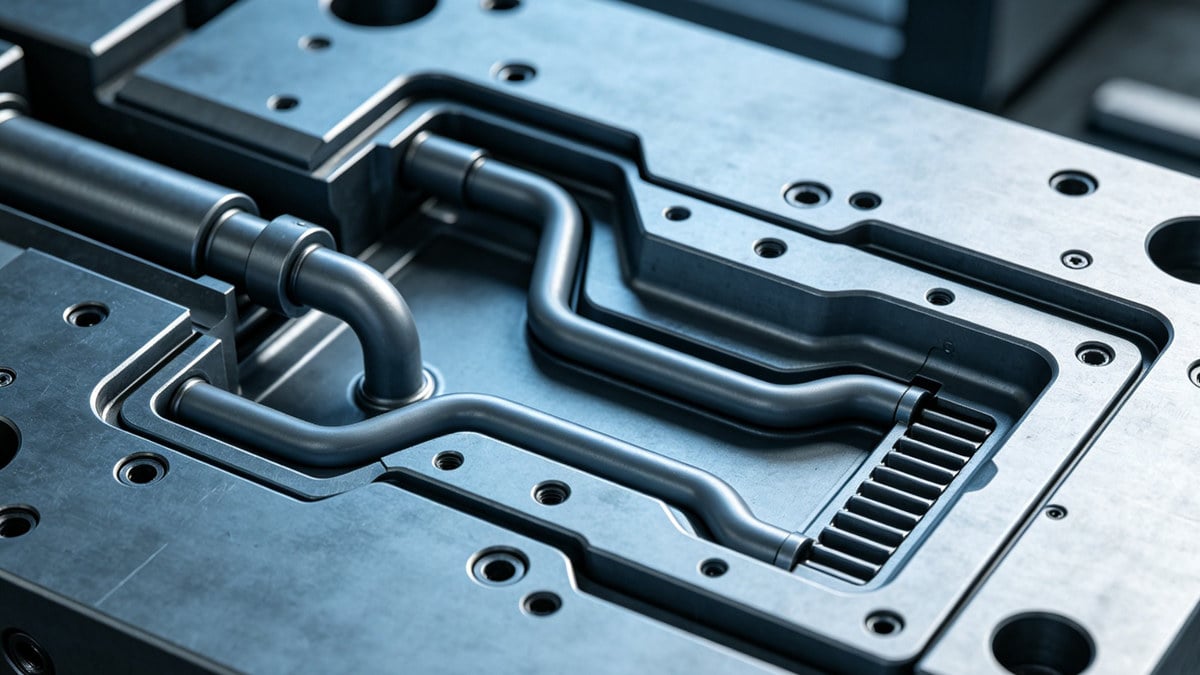
At Ideal Pro, we offer end-to-end custom solutions. We know that a good part starts with a good mold design. Mold steel modification is treated only as the last resort, but sometimes it is completely necessary.
Gate and Runner Size
The runner is the channel that carries plastic to the part. The gate is the door. If the door is too small, the plastic has to squeeze through. This squeezing causes the plastic to slow down and cool off. We always check if the gate is big enough for the part size. We make runners short and thick to keep the heat inside the plastic.
The Importance of Venting
When plastic goes into a mold, air must come out. If you have insufficient venting, the air gets trapped. Trapped air acts like a wall. It pushes against the plastic melt. This fight between air and plastic causes the melt front to stutter and leave marks. We cut tiny vents to let the air escape. Read more about injection mold venting issues and solutions to understand how vent design impacts your parts.
| Tooling Feature | Bad Design | Impact on Flow |
|---|---|---|
| Gate | Too small or wrong place | High pressure loss |
| Runner | Too long or thin | Heat loss before cavity |
| Vents | Too shallow or missing | Air traps block the flow |
Can Wall-Thickness Variation and Part Structural Issues Lead to Flow Marks?
Uneven walls make plastic flow in weird ways. If your part design is flawed, defects will appear. Let us see how part structure affects the flow.
Yes, sudden changes in wall thickness cause flow marks. When plastic moves from a thick section to a thin section, it slows down and cools rapidly. This hesitation creates a wavy pattern. Designing parts with uniform wall thickness keeps the plastic flow steady and prevents defects.
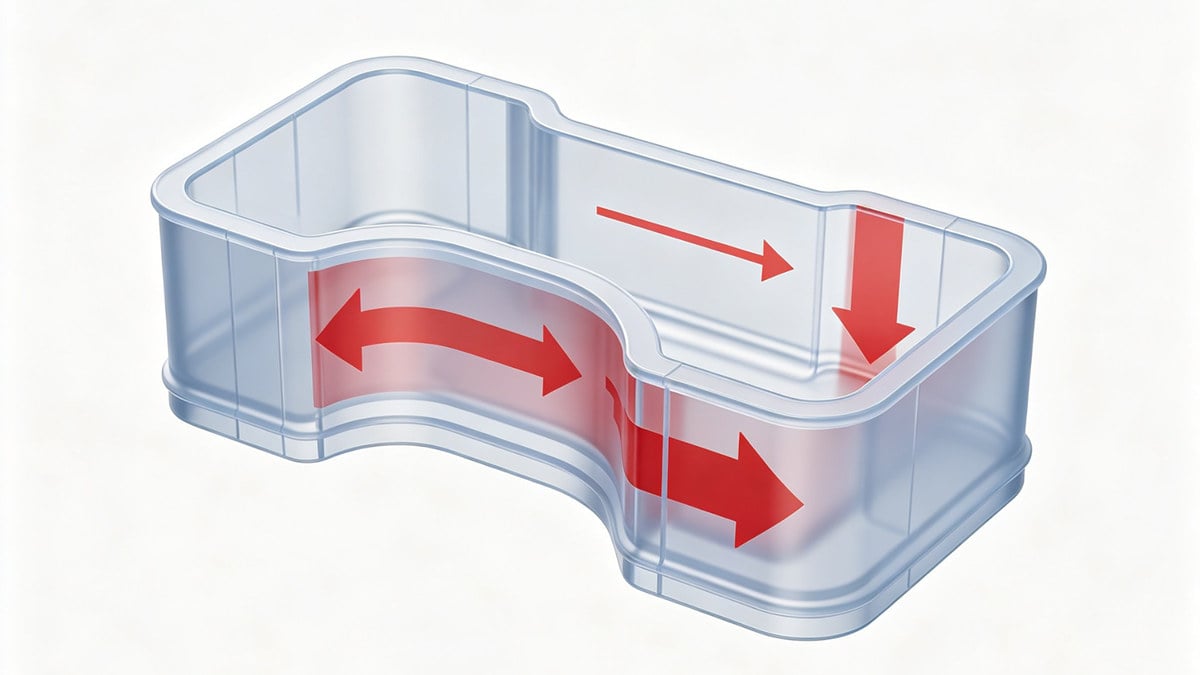
Before we cut any steel, we do a DFM analysis. DFM stands for Design for Manufacturability. We look at the part design to find problems early. Understanding how wall thickness affects the quality of plastic parts is critical during this stage.
The Problem with Uneven Walls
Plastic likes to take the easiest path. It flows very fast through thick walls. It flows very slow through thin walls. If your part has thick and thin areas right next to each other, the plastic gets confused. It races through the thick part and stalls at the thin part. This uneven speed ruins the part surface.
How Hesitation Causes Marks
When the flow stalls at a thin wall, it hesitates. During this hesitation, the plastic cools down. By the time the pressure builds up enough to push the plastic through the thin area, the outer layer is already cold. This leaves a permanent wavy mark on the surface. We always try to make walls exactly the same thickness.
| Part Feature | Flow Behavior | Defect Risk |
|---|---|---|
| Uniform Walls | Steady speed | Low risk |
| Thick to Thin Transition | Flow hesitates | High risk of flow marks |
| Sharp Corners | Flow breaks apart | High risk of turbulence |
How Do Material Viscosity, Moisture, and Contamination Affect Flow Marks?
Wet or dirty plastic ruins the injection process. If you ignore material handling, your parts will look terrible. Let us examine how raw materials cause issues.
High material viscosity makes plastic stiff and hard to push, leading to slow, uneven flow. Moisture in the raw material creates steam, which disrupts the melt front. Contamination from dust or old plastic changes the melting point, causing inconsistent flow and wavy marks on the part.
You must treat your raw materials with care. Bad plastic makes bad parts. We always verify raw-material drying and handling before we start the machines.
Understanding Viscosity
Viscosity means how thick the liquid plastic is. Water has low viscosity. Honey has high viscosity. If you choose a plastic with very high viscosity, the machine has to work very hard to push it. If the machine cannot push hard enough, the flow slows down and creates flow marks. You can add special lubricants to the plastic to help it flow better.
Moisture and Dirt
Many plastics absorb water from the air. If you do not dry the plastic, the water turns into steam inside the hot machine barrel. This steam bubbles up and ruins the smooth flow of the plastic. Dirt and old plastic do the exact same thing. We clean our hoppers every day.
| Material Issue | Effect on Plastic Melt | Result on Part |
|---|---|---|
| High Viscosity | Very stiff and slow | Wavy flow marks |
| Wet Material | Steam bubbles form | Splay and flow marks |
| Contamination | Unmelted particles | Bumps and flow disruptions |
What Is the Systematic Troubleshooting Workflow for Flow Marks?
Guessing the solution wastes hours of machine time. You need a clear step-by-step plan. Here is the exact workflow we use to fix flow marks fast.
We always follow a practical workflow: fine-tune process parameters first, verify raw-material drying and handling, then optimize gate, runner, and cooling layout. Mold steel modification is treated only as the last resort. This step-by-step method prevents wasted time and protects your expensive mold from unnecessary changes.
When I stand in front of a broken machine, I do not panic. I follow our Ideal Pro standard workflow. It saves time and stops mistakes.
Step 1: The Process
First, I look at the machine screen. I check the temperatures and the injection speeds. I make small changes to the speed profile. I increase the mold heat. Process changes are free and fast. I never touch the mold until the process is perfect.
Step 2: The Material
If the machine settings look good, I check the plastic. Is the dryer working? Is the hopper clean? Are we using the right grade of plastic?
Step 3: The Mold
If the process and material are perfect, the problem is the mold. I look for blocked vents or bad cooling lines. I only ask the tool shop to cut the steel and make the gate bigger if nothing else works.
| Troubleshooting Step | Action Taken | Cost and Time |
|---|---|---|
| 1. Process Settings | Adjust speed and heat | Fast and Free |
| 2. Material Check | Verify drying and purity | Fast and Low Cost |
| 3. Mold Layout | Clean vents, check cooling | Medium Time and Cost |
| 4. Steel Modification | Widen gates, add vents | Slow and Expensive |
What Are the Actionable Fixes for Existing Flow Mark Issues?
Do you need to fix a running job right now? Stop the machine and try these exact steps. Let us eliminate those flow marks today.
To fix existing flow marks quickly, increase the injection speed to push the plastic faster. Raise the barrel and mold temperatures to keep the melt hot. Create a multi-stage speed profile that starts slow at the gate, speeds up in the middle, and slows down at the end.
You can often save a bad production run with a few smart adjustments. Here is exactly what I do on the factory floor when a client needs help fast.
Adjusting the Heat
First, I turn up the mold temperature controller. A hot mold lets the plastic flow much further before it freezes. Next, I increase the melt temperature in the barrel by 5 to 10 degrees. I wait ten minutes for the heat to soak in, then I run a few parts. Heat is usually the best cure for flow marks.
Tuning the Speed
If the heat does not fix it, I change the injection speed. I set the machine to inject slowly right as the plastic goes through the gate. Then, I tell the machine to push very fast to fill the main body of the part. This multi-stage approach almost always smooths out the wavy lines.
| Actionable Fix | How to Do It | Why It Works |
|---|---|---|
| Increase Mold Temp | Turn up water heater | Stops plastic from freezing fast |
| Increase Melt Temp | Raise barrel heaters | Makes plastic flow easier |
| Multi-Stage Speed | Slow-Fast-Slow setting | Controls the melt front perfectly |
How Can You Prevent Flow Marks at the DFM and Mold-Design Stage?
Fixing a mold after it is built costs thousands of dollars. You must catch problems early. Let us see how good design stops defects before they start.
Prevent flow marks during DFM by designing parts with uniform wall thickness and smooth transitions. For mold design, place the gate at the thickest part of the product. Ensure the runner system is large enough and add deep vents at the end of the flow path.
At Ideal Pro, we believe in doing things right the first time. Our DFM analysis finds flow mark risks before we cut any metal. This saves our clients a huge amount of money.
Smart Part Design
We tell our clients to avoid sudden thickness changes. We use large radiuses on corners instead of sharp angles. Smooth curves help the plastic flow like a gentle river instead of a crashing waterfall. A good part design makes injection molding very easy.
Clever Gate Placement
Where you put the gate changes everything. We always put the gate in the thickest section of the part. The plastic flows from thick to thin. This keeps the pressure high and the flow steady. If you flow from thin to thick, the plastic will hesitate and leave marks every single time.
| Design Stage | Best Practice | Benefit |
|---|---|---|
| Part DFM | Uniform wall thickness | Stops flow hesitation |
| Mold Layout | Gate at thickest section | Maintains high pressure |
| Venting Plan | Vents at flow ends | Stops air from blocking plastic |
Can Mold-Flow Simulation Help Predict Flow Marks?
Guessing how plastic fills a mold is a gamble. If you guess wrong, you ruin the tool. Let us use technology to see inside the mold.
Yes, mold-flow simulation software predicts flow marks with high accuracy. It creates a digital model of the injection process. The software shows you exactly where the plastic slows down, where it loses heat, and where air gets trapped. This allows engineers to fix the mold design early.
We do not like to guess. We use advanced computer software to simulate the plastic injection process. It is a powerful tool for our engineering team.
Seeing the Unseen
Mold-flow software shows us a colorful video of the plastic filling the part. We can see the temperature of the plastic at every single second. If the software shows a spot where the plastic gets too cold, we know a flow mark will happen there. We can fix it on the computer screen.
Saving Time and Money
Running a computer simulation takes a few hours. Rebuilding a real steel mold takes weeks and costs a lot of money. We use the software to test different gate sizes and cooling channel layouts. We find the perfect setup on the computer first, so the real mold works perfectly on day one.
| Simulation Output | What It Shows | How It Helps |
|---|---|---|
| Temperature Map | Cold spots in mold | Move cooling channels |
| Velocity Vectors | Speed of plastic flow | Fix hesitation spots |
| Air Trap Locations | Where air gets stuck | Add vents in exact spots |
What Are the Common Mistakes When Trying to Fix Flow Marks?
Panicking on the factory floor leads to bad decisions. If you change five settings at once, you will get lost. Let us avoid these common traps.
The most common mistake is misdiagnosing flow marks as jetting or weld lines. Another mistake is changing too many machine settings at the same time. Operators often increase injection pressure too much, which causes flash, instead of fixing the real problem like low mold temperature.
I have watched many new technicians make a bad situation worse. They try to work too fast. They skip the basic rules of injection molding.
One Change at a Time
Never change the speed, the pressure, and the heat all at once. If the part gets better, you will not know which change actually fixed it. I always change one single setting. Then I wait. I run five parts. I look at the results. This patient method always works best.
The Pressure Trap
When plastic does not fill properly, people love to increase the injection pressure. High pressure forces the plastic into the mold. But it also forces plastic into the tiny cracks of the mold, creating a new defect called flash. You must fix the heat and speed first, not just force it with high pressure.
| Bad Habit | Why It Is Bad | Better Approach |
|---|---|---|
| Wrong Diagnosis | You fix the wrong thing | Learn defect differences |
| Multiple Changes | You get lost in the data | Change one setting at a time |
| Maxing out Pressure | Causes mold damage and flash | Fix heat and speed profiles |
What Are the FAQs on Injection Molding Flow Marks?
Do you still have questions about these annoying wavy lines? You are not alone. Let us answer the most common questions our clients ask us.
Clients often ask if flow marks weaken the part. Yes, they can create internal stress. They also ask if all plastics get flow marks. High-viscosity plastics like PC or ABS are much more likely to show flow marks than easy-flowing plastics like PP or PE.
We believe in sharing knowledge with our partners. Here are the simple answers to questions I hear every single week from our clients.
Are Flow Marks Just Cosmetic?
No. While they look bad, they also mean the plastic did not fuse perfectly. If you are making a simple toy, a flow mark might be okay. But if you are making a car part that takes a lot of force, that flow mark is a weak spot that could fail.
Can I Polish the Mold to Fix It?
Polishing the mold makes the steel shiny. It does not fix the plastic flow. In fact, a highly polished mold makes flow marks easier to see! You must fix the process, not just shine the steel. Fixing the flow is the only real answer.
| Common Question | Short Answer | Detailed Reason |
|---|---|---|
| Do they weaken parts? | Yes, sometimes | Uneven cooling creates internal stress |
| Does plastic type matter? | Yes, very much | Stiff plastics show marks easily |
| Will polishing fix it? | No, never | It only highlights the defect |
What Are the Best Practices for a Defect-Free Surface Finish?
Producing ugly parts hurts your business reputation. You need a reliable system for perfect quality. Let us review the best rules for a flawless surface finish.
To achieve a defect-free surface finish, maintain stable melt and mold temperatures. Use a multi-stage injection speed profile to control the melt front. Ensure raw materials are completely dry. Always rely on a systematic troubleshooting workflow, checking the process first before ever cutting the mold steel.
At Ideal Pro, we deliver superior quality and fast turnaround. We do this by following strict rules for every single project. We never cut corners.
Consistent Setup is Key
You cannot have a perfect surface if your setup changes every day. We write down the exact water temperatures, barrel heats, and speed profiles for every mold. We use this exact setup every time we run the job. If you want to explore more surface defect solutions, check our guide on injection molding surface defects: root causes and practical solutions.


 English
 French
 Dutch
Dutch German
 Japanese
 Korean