 한국어




The truth? Injection molding isn’t a linear pipeline. It’s a feedback-driven system, where a flaw in Step 1 (design) echoes through Steps 5–8 as warpage, sink, or inconsistent dimensions.
This guide goes beyond “clamping → injection → cooling”. We’ll walk you through the 8 critical phases — plus the 3 hidden control loops that separate functional parts from profitable, scalable production.
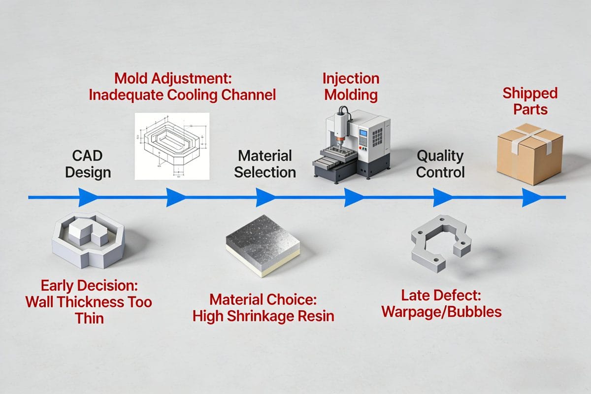
The process of injection molding can be daunting, especially when striving for zero-defect manufacturing. The challenges are numerous, but understanding the key phases can make all the difference. Let's dive into each phase to ensure we're not just producing parts, but producing them with precision and consistency.
Phase 1: Design for Moldability (DFM) — Where 87% of Failures Begin?
Most teams treat DFM as a checklist. Top shops treat it as physics-based constraint solving.
Key Rules You Can’t Ignore:
- Wall thickness ratio ≤ 1.5:1 (not 2:1!) — otherwise, differential shrinkage causes sink even with perfect packing.
- Ribs must be ≤ 60% nominal wall — and include draft ≥ 1° on both sides. No exceptions.
- Gate location isn’t about convenience — it’s about flow front symmetry. Use Moldflow’s Fill Time Difference map ( ? Pro Tip: Run a “Shrinkage Sensitivity Analysis” in your CAE tool:
>ΔDimension / ΔMeltTemp> 0.02 mm/°C? Redesign — your process window is too narrow.
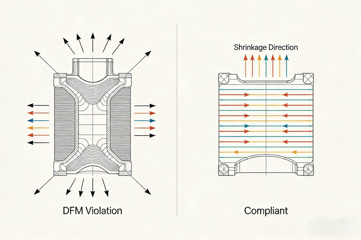
Understanding the intricacies of design for moldability is crucial. Many designers overlook the physics at play. Properly accounting for wall thickness and rib dimensions can prevent issues down the line. Ribs serve a purpose, but if they’re not designed right, they can lead to major headaches.
Phase 2: Mold Engineering — Beyond Cavity & Core?
A mold isn’t just steel. It’s a thermal-fluid system.
Must-Validate Subsystems:
| Subsystem | Failure Mode | Validation Method |
|---|---|---|
| Cooling Circuit Balance | Warpage from ΔT > 3°C across cavity | Infrared thermography @ 10k cycles |
| Ejector Pin Layout | Sticking or mark due to uneven force | FEA of ejection stress (max ⚠️ Reality Check: 42% of “material degradation” claims are actually poor venting — confirmed via gas chromatography of burnt residue. |
In mold engineering, the focus must be on proper thermal management. If cooling isn’t balanced, warpage can become a serious issue. It’s not just about the mold’s design; it’s also about how it interacts with the material during processing. Proper validation will save time and money in the long run.
Phase 3: Material Selection — It’s Not Just MFI?
MFI (Melt Flow Index) is a starting point — not a specification.
The Real Triad:
- PVT Behavior — How does specific volume change with P & T? (Critical for shrink prediction)
- Crystallinity Kinetics — For semi-crystalline resins, gate freeze time = f(crystallization onset temp)
- Moisture Sensitivity — PC hydrolyzes at >0.02% moisture → molecular weight drop → brittle parts
> ✅ Action: Request PVT database files (.pvtd) from your resin supplier — import into Moldflow for ±0.05 mm dimensional accuracy.
Material selection can make or break the process. Understanding PVT behavior is critical. If we only focus on MFI, we miss key factors that affect the final product. Each resin behaves differently under varying temperatures and pressures. Knowing these behaviors helps predict issues before they happen.
Phase 4: Process Development — The 3-Layer Tuning Framework?
Forget “fill 98%, pack 80 MPa”. Use this:
Layer 1: Physics-Based Baseline
- Set initial transfer via short-shot + weight inflection (not screw pos)
- Hold pressure = 50–70% of injection peak (amorphous) or 60–80% (semi-crystalline)
Layer 2: Cavity Pressure Closed Loop
- Trigger V/P switch when dP/dt > 7 bar/ms at gate sensor
- Ramp hold pressure down over 0.3–0.5s to reduce residual stress
Layer 3: Statistical Robustness
- Run L9 DOE on: Transfer %, Hold Pressure, Hold Time
- Target: CPK ≥ 1.67 on critical dimension
- Monitor with X̄-R charts — alarm if σ > 0.015 mm
Process development requires a structured approach. The three-layer tuning framework is essential. It shifts our focus from merely filling molds to understanding the physics behind each step. Monitoring these layers allows for real-time adjustments that can prevent defects before they occur.
Phase 5: Transfer Position Deep Dive — The Make-or-Break Moment?
→ See your prior 6-section deep dive, but restructured as:
- Why 97.3% ≠ 97.3% (material/mold dependency)
- Dual-sensor ΔP rate as gold standard
- Multi-cavity sync protocol (per-cavity offset tables)
- Cost of mis-transfer: $4,324/batch quantified
The transfer position plays a crucial role in maintaining quality. If not set correctly, even minor adjustments can lead to significant defects. Using dual-sensor systems and syncing multi-cavity setups can dramatically improve consistency across the board.
Phase 6: First Article Validation — Beyond Dimensional Check?
Don’t just measure length/width. Validate the 4 Pillars:
- Internal Stress — Photoelasticity or hole-drilling strain gauge
- Weld Line Strength — Micro-tensile test at weld vs. bulk
- Gate Vestige Height — Laser profilometer (target: ≤ 0.03 mm)
- Cycle Time Stability — σ of cycle time ? Example: A connector passed dimensional check (CPK=1.8) but failed drop test — root cause: high residual stress at rib base (measured 28 MPa vs. max allowed 15 MPa).
First article validation must go beyond surface-level checks. Focusing on internal stress and weld line strength is essential for ensuring the part's integrity during usage. Testing every aspect can prevent costly failures later in the production cycle.
Phase 7: Production Ramp-Up — The Hidden Killers?
Scaling from 100 to 10,000 pcs/day fails due to:
- Resin lot drift (MFI ±15% → transfer shift of 0.6%)
- Chiller temperature creep (+2°C → gate freeze time +0.12s)
- Check ring wear → barrel slip → false screw-position trigger
Mitigation Protocol:
- ✅ Lot Qualification Matrix: Test new resin batch against golden part (CTQs only)
- ✅ Auto-Compensation Script: If melt temp drifts > ±3°C, adjust transfer % by −0.2%/°C
- ✅ Weekly Sensor Recalibration: Using short-shot reference
Ramp-up can be full of surprises. Monitoring resin lots and ensuring the temperature remains stable is critical. Having a mitigation plan in place can prevent small issues from turning into costly production delays.
Phase 8: Continuous Improvement — Closing the Loop?
Top performers use:
- Digital Twin Sync: Real machine data → update Moldflow material model weekly
- Defect Root-Cause AI: NLP on shop floor logs + cavity pressure → auto-tag “transfer too late” for sink marks
- OEE Breakdown by Phase: e.g., “Clamping loss: 4.2% due to mold heating cycle”
> ? Final Truth: The best injection molding line doesn’t make perfect parts.
> It makes predictably good parts — and knows why when they’re not.
Continuous improvement is the backbone of any successful operation. Utilizing data and adapting processes can lead to better outcomes over time. Embracing a culture of learning ensures that each cycle improves upon the last, driving efficiency and quality.
결론
Injection molding isn’t magic. It’s applied polymer physics, precision mechanics, and disciplined data discipline. Start with DFM that respects material behavior. Tune transfer using cavity pressure — not hope. Scale with closed-loop compensation — not heroics.
Do this, and you won’t just produce parts.
You’ll own the process.
저자 소개

Alex Yu
아이디얼 프로 매뉴팩처링
알렉스는 Ideal Pro의 공동 창립자이지만, 주요 프로젝트를 총괄하거나 기술 팀을 이끌지 않을 때는 장거리 자전거 타기를 즐기거나, 동네에서 가장 맛있는 커피를 찾아다니거나, 다음 여행 계획을 세우는 모습을 볼 수 있습니다. 국제 무역 영업과 프로젝트 관리 분야에서 20년 이상의 경력을 쌓아온 그는 촉박한 마감 기한부터 까다로운 엔지니어링 문제까지, 그 사이의 모든 상황을 다 겪어보았습니다. 그는 훌륭한 성과는 충분한 휴식을 취한 마음과 맛있는 커피에서 나온다고 믿으며, 맡은 모든 프로젝트에 그와 같은 호기심과 세심한 주의를 기울입니다. 사무실에 있지 않을 때는 대개 야외 어딘가에서 새로운 장소를 탐험하며, 나중에 나눌 이야기를 수집하곤 합니다.
 English
 French
 Dutch
 German
 Japanese
 Korean