 日本語



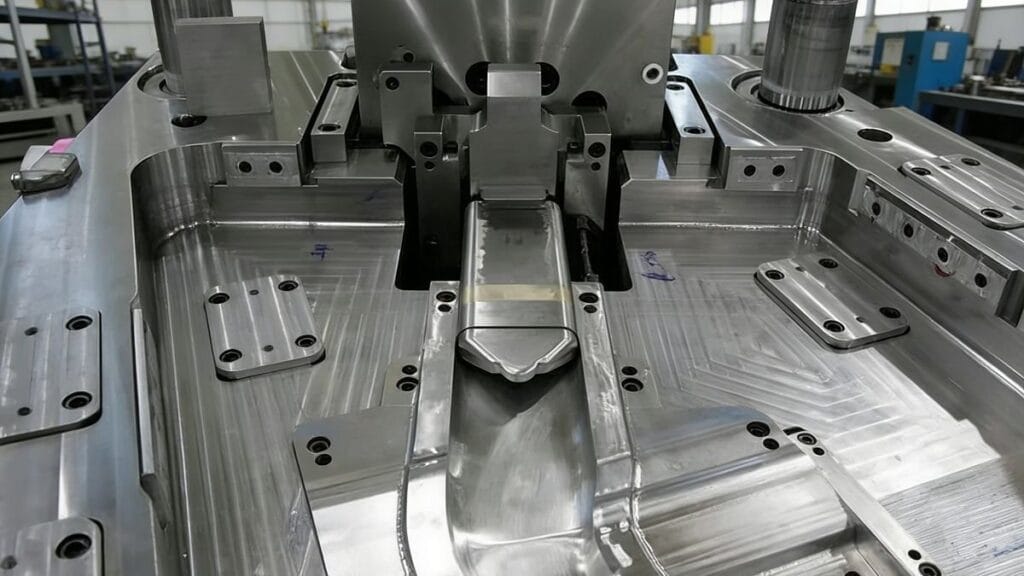
In 射出成形[^1], mold design directly determines product quality, production efficiency, and manufacturing costs. Below is a comprehensive breakdown of the core design principles, procedures, and key systems that guide professional injection mold development.
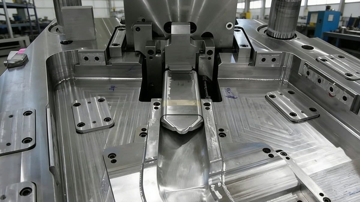
Core Design Basis
1. Dimensional Accuracy & Correctness of Related Dimensions
The external quality and specific dimensions of plastic products are defined by their functional requirements:
- Appearance-focused products (e.g., toys): High aesthetic standards but moderate dimensional precision.
- Functional products: Strict dimensional tolerances to ensure performance.
- High-precision products (e.g., cameras): Stringent requirements for both appearance and dimensions.
2. Rationality of Draft Angle[^2]
The draft angle is critical for smooth demolding and product integrity:
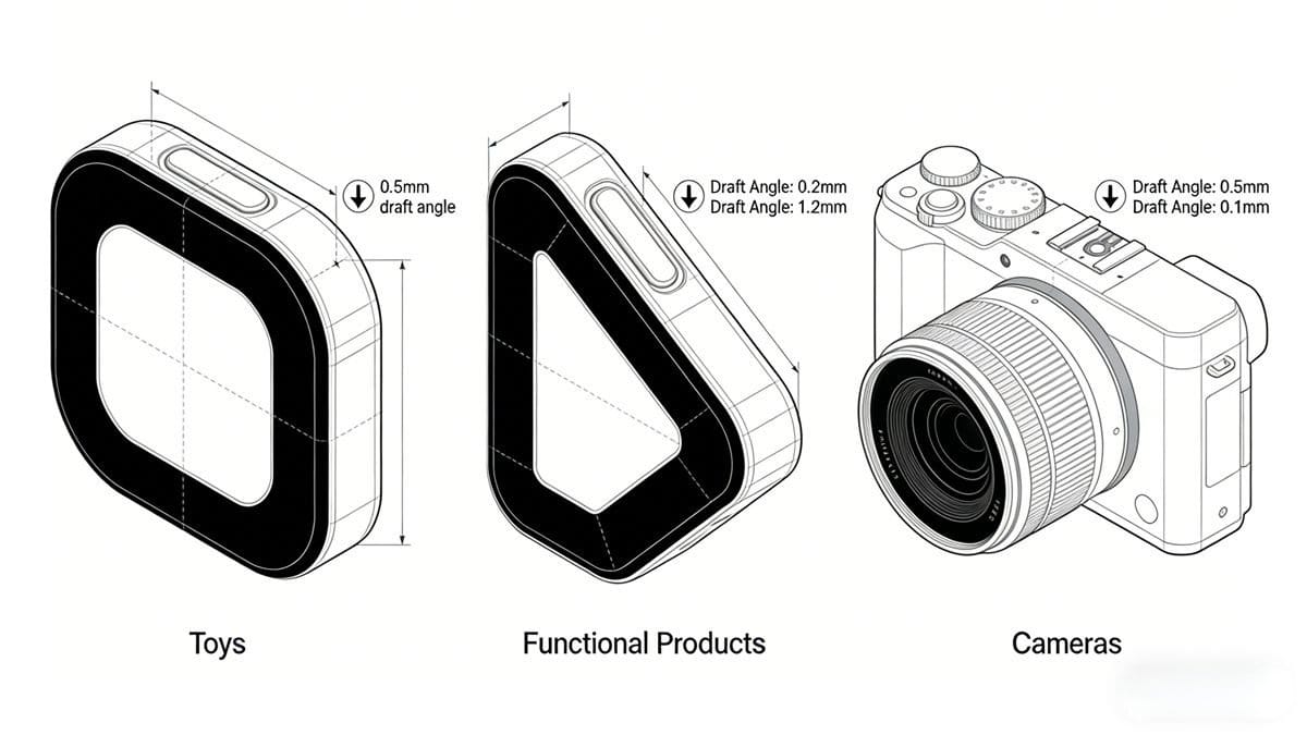
- Ensure sufficient draft to prevent sticking during ejection.
- Align the angle with the parting/split mold surface.
- Avoid compromising appearance or wall thickness accuracy.
- Prevent weakening of critical structural areas.
Standard Design Procedure
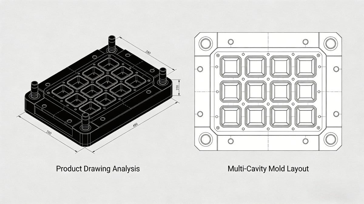
1. Analysis of Product Drawings & Physical Samples
Thoroughly evaluate the product to establish design constraints:
- Geometric shape and structural complexity.
- Dimensional specifications, tolerances, and design datums.
- Technical requirements (e.g., strength, flexibility).
- Plastic material grade and surface finish demands.
2. Cavity Quantity & Layout
Determine the number of cavities based on:
- Product weight vs. injection machine capacity.
- Projected area vs. clamping force.
- Mold size vs. machine’s tie-bar spacing.
- Product precision, color, and production volume.
- Economic efficiency (output value per mold).
Cavity Layout Considerations:
- Optimize mold size and gating system balance.
- Coordinate with core-pulling mechanisms, inserts, and cooling systems.
- Adjust based on parting surface and gate position selection.
Key Design Elements
1. Parting Surface Selection
The parting surface should:
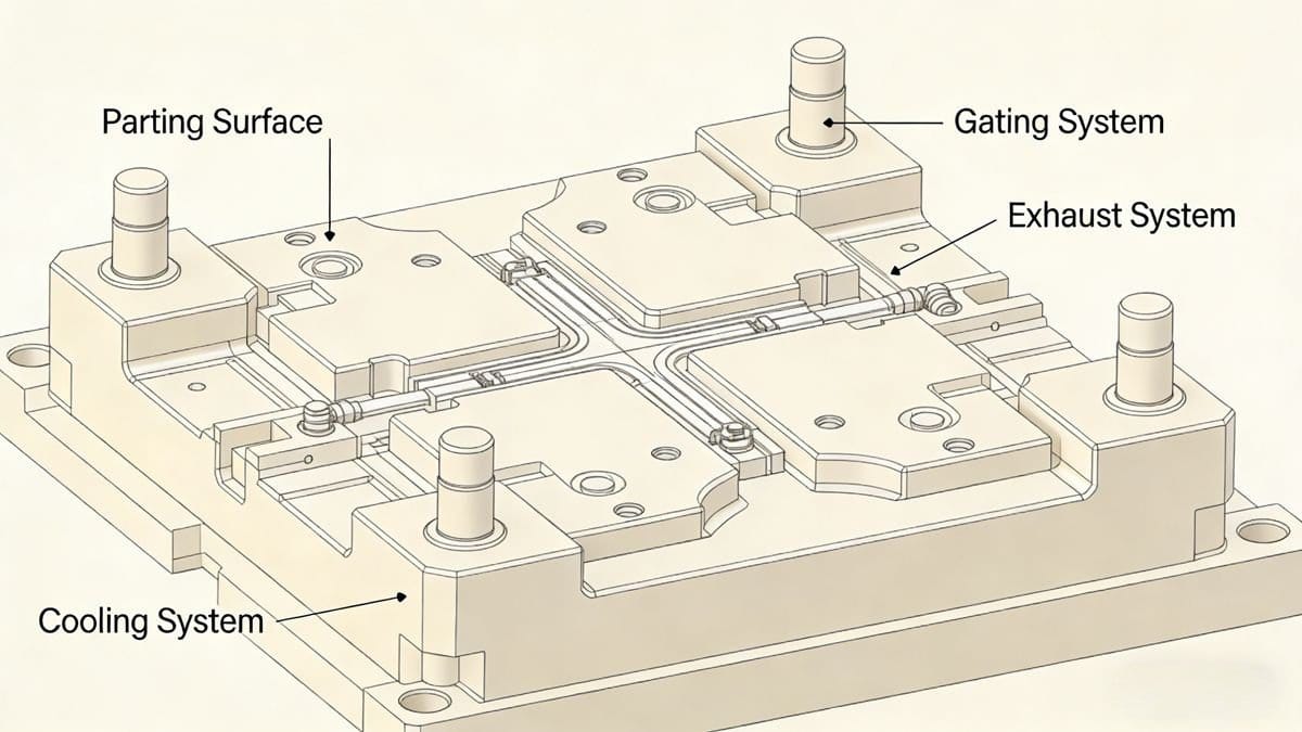
- Preserve product appearance and precision.
- Simplify mold machining (especially cavity fabrication).
- Facilitate gating, exhaust, and cooling system integration.
- Ensure the product remains on the 動く金型 during demolding.
- Accommodate metal inserts easily.
2. Gating System Design
The gating system controls plastic flow into the cavity. Key steps:
- Gate Position Selection (follow these principles):
- Locate on the parting surface for easy cleaning.
- Ensure equal distance to all cavity areas (shortest flow path).
- Direct flow toward thick-walled sections for smooth filling.
- Avoid impinging on cores/inserts (prevents deformation).
- Minimize weld lines or place them in non-critical areas.
- Enable uniform filling and efficient gas evacuation.
- Position for easy post-processing without affecting appearance.
- System Components:
- Sprue: Main channel connecting the injection machine to the mold.
- Runner: Distributes plastic to multiple cavities (optimize cross-section for flow).
- Gate: Controls flow rate and pressure (e.g., pin-point, edge, or sub-gates).
- Degating Mechanism: For pin-point gates, ensure runner separation during ejection.
3. Exhaust System Design
Effective venting prevents defects like air traps and burn marks:
- Vent Grooves: Position at the last-filled cavity areas. Depth varies by material:
- ABS: ≤0.04 mm
- Putty: ≤0.02 mm
- POM (Delrin): ≤0.02 mm
- Clearance Venting: Use gaps between cores, ejector pins, or special exhaust plugs.
- Air Pins: Prevent vacuum deformation during product ejection.
- Anti-Vacuum Components: Avoid product adhesion to the mold surface.
4. Cooling System Design[^3]
Uniform cooling ensures consistent product quality and cycle time reduction. Design considerations:
- Cooling channel layout (e.g., parallel, series, or spiral).
- Position and size of channels (avoid interfering with other mold components).
- Targeted cooling for high-heat areas (e.g., cores, inserts, sliders).
- Selection of standard cooling components (pipes, baffles, O-rings).
- Sealing structure to prevent water leakage.
> 注記 > > Injection mold design is a iterative process—each system interacts with others. Balancing functionality, manufacturability, and cost requires careful adjustment based on specific product requirements.
[^1]: Explore this resource to gain in-depth knowledge about injection molding, enhancing your design and production efficiency. [^2]: Exploring this will help you grasp how draft angles influence product integrity and demolding efficiency. [^3]: Effective cooling design is crucial for maintaining product quality and reducing cycle times.
著者について

アレックス・ユー
アイデアル・プロ・マニュファクチャリング
アレックスはIdeal Proの共同創業者ですが、重要なプロジェクトの監督や技術チームの指揮をとっていないときは、長距離サイクリングを楽しんだり、街で一番おいしいコーヒーを探し回ったり、次の旅の計画を立てたりしている姿を見かけるでしょう。 国際貿易の営業やプロジェクト管理に20年以上の経験を持つ彼は、厳しい納期や厄介な技術的課題など、ありとあらゆる状況を経験してきました。彼は、素晴らしい仕事は十分な休息と一杯の美味しいコーヒーから生まれると信じており、その好奇心と細部へのこだわりを、手掛けるすべてのプロジェクトに注ぎ込んでいます。 オフィスにいないときは、たいてい屋外で、新しい場所を探索したり、皆と共有できるエピソードを集めたりしています。.

 English
 French
 Dutch
 German
 Japanese
 Korean