 Français



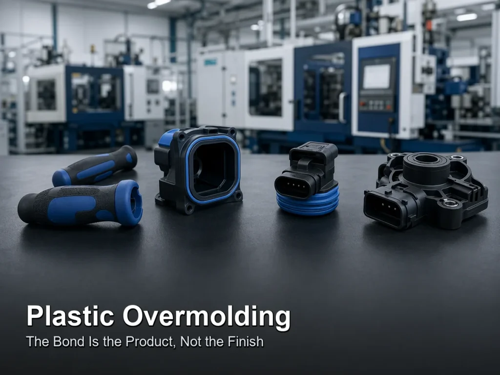
TL;DR, the honest version: an overmold that passes the first 200 samples can still peel in the field, because the part you approved was never the part that failed. Plastic overmolding succeeds or dies at the interface — a bond created by heat, pressure, chemistry and geometry in the same eight seconds. Get the substrate material, the surface energy, the melt temperature and the mechanical keying right together and the part outlives its housing. Get one of them wrong and you have purchased a two-material delamination problem with nice colours. This guide is the definitional pillar for everything else we publish on the subject: what overmolding actually is, the four mechanisms that create adhesion and how they rank, the geometry numbers we design to, which material pairs bond without primer, what the process does to your tooling, and how to prove the bond before you commit to a production run.
A buyer once sent us a soft-grip handle that had failed at 40,000 units: the TPE lifted off the PC substrate in a clean ring around the grip, leaving the plastic underneath untouched. Nothing about the drawing was wrong. The substrate had sat on a shop floor for nine days and picked up a mould-release silicone film nobody counted as a contaminant. The overmold was fine. The surface was not.
Key Takeaways
- The interface, not the elastomer, sets the life. A soft-touch layer almost never fails by tearing; it fails by releasing. Design the bond first and the durometer second.
- Four mechanisms make adhesion, and they are not equal. Mechanical interlock survives abuse, molecular diffusion survives solvents, chemical bonding survives a decade, and simple wetting survives about nothing. Know which one you paid for.
- PP and TPE are a trap. Polypropylene substrate plus standard TPE is a low-energy, non-polar pairing that will not bond without a modified PP-based TPE or primer — the most common silent failure we get asked to diagnose.
- Two-shot and pick-and-place are different purchases. Rotary index accuracy, second-shot clamp tonnage, shut-off wear and venting for outgassing elastomers change the tool quote, not just the cycle time.
- Prove the bond with artefacts. Peel values, thermal-cycle counts, cavity-level identification and an IP verification on the actual geometry — not an adhesion adjective in an email.
Why Trust This Overmolding Guide?
Because we make both halves of the part. Ideal Pro runs mould design, tooling, molding and finishing under one ISO 9001:2015 system in Huzhou, on presses up to 1,600 tons, building over a thousand mould sets a year for customers in more than fifty countries. That matters here for one specific reason: in overmolding, the person who quotes the second shot is normally the person who has to explain the delamination, so the arithmetic stays honest.
Where this guide gives a number, it is either our own published shop standard, an arithmetic result on stated assumptions, or a working range we use to start a conversation — labelled every time. Where a claim would depend on your resin lot, your adhesive primer, your wall geometry or your certification path, we say it depends rather than inventing a universal figure that would read better and cost you more. We hold ISO 9001:2015 with RoHS and FCC documentation; we do not hold IATF 16949 or an implant-class medical device path, and a large share of overmolded demand sits in exactly those two lanes.
Quick Reference Guide: Overmolding VS. Insert Molding VS. Two-Shot VS. Assembly
Four things get called overmolding. They buy you different things, and choosing between them at the quote stage is a ten-minute conversation instead of a five-week re-tool.
| Méthode | What is inside the part | Tooling consequence | Buy it when |
|---|---|---|---|
| Overmolding (general) | A substrate of any kind — plastic, metal, sintered — enveloped or partly covered by a second moulded material | Two tools plus a second-station tool that locates on the cured first part | You need a permanent, integrated multi-material part |
| Insert molding | Usually pre-made metal: threaded bushings, terminals, shafts | Steel-to-plastic locating, thermal mismatch management, often hand or robotic loading | You need pull-out strength in a metal interface |
| Two-shot / 2K | A first-shot plastic part, still hot, indexed to a second cavity | Rotary or multi-platen tool, index repeatability, higher tool entry cost | High volume, best bond, no operator in the loop |
| Mechanical assembly | Adhesive, snap-fit or press-fit separate parts | No second-shot tool, but labour, adhesive cure and tolerance stack | Low volume, serviceability, or materials that refuse to bond |
Overmolding and insert molding are frequently confused on purpose by suppliers quoting one tool when the drawing needs two. Our insert molding capability page and the two-shot versus overmolding comparison draw the line in detail; the short version is that insert molding is a subset of overmolding where the insert came from somewhere else.
What Is Plastic Overmolding, Really?
Plastic overmolding is a multi-material injection moulding process in which a second polymer is moulded directly onto a pre-existing substrate, creating a single part whose interface is formed during processing rather than joined afterwards. The defining test is not that two materials exist. It is that the second material was molten, under pressure, at temperature close to its melting point, against a surface that was chosen and prepared for it.
That distinction is worth arguing about, because a lot of published guides describe overmolding as a finishing technique that “enhances the look” of a component. It is not. If the second layer can be removed without damaging the part, you did not overmold — you assembled, potted, dipped or painted. Overmolding is a core forming step: the interface is created inside the tool, in the same thermal environment that determines the crystallinity and orientation of both materials, and it cannot be revisited after the mould opens.
The practical categories we run:
- Soft-touch over rigid: TPE, TPU or silicone over ABS, PC, PC/ABS, PA. Grip, damping, seal, perceived quality.
- Rigid over flexible: a hard housing or boss moulded onto a rubber body, common in vibration mounts and buttons.
- Sealing over electronics and connectors: elastomer moulded to a connector body or a board; see our PCB overmolding guide for the low-pressure branch of this, where the constraint is component survival rather than adhesion.
- Colour and identity overmolding: a second colour as a functional indicator, keys and bezels, where the bond requirement is cosmetic longevity, not structural.
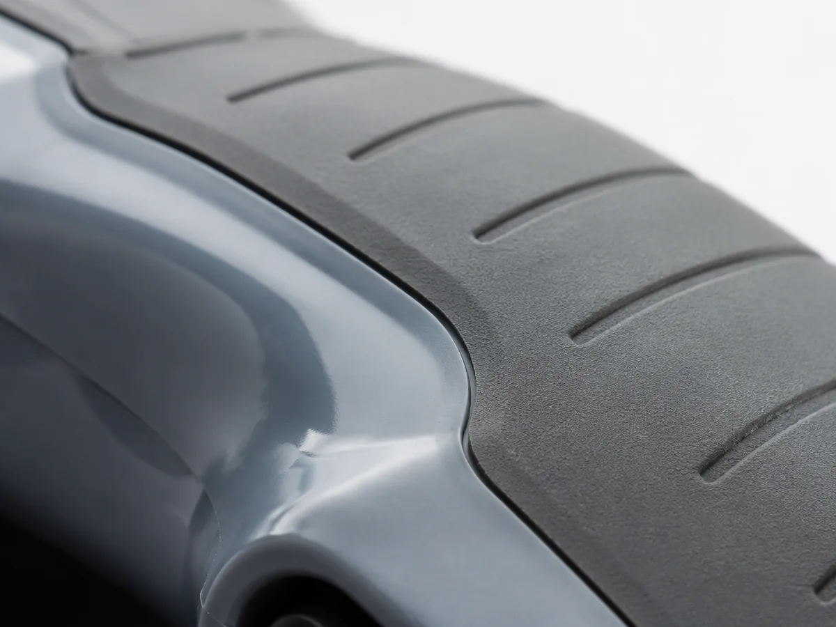 Figure 1: Macro of a TPE-over-PC interface. The visible line is where every failure in this process actually starts.
Why Do Overmolds Delaminate? Four Bond Mechanisms, Ranked
Overmold adhesion is the sum of up to four distinct mechanisms — mechanical interlock, molecular diffusion, chemical bonding, and adsorption (wetting) — and they contribute in roughly that order of robustness. A successful overmold usually has at least two working at once. One mechanism alone is a field-return generator.
1. Mechanical interlock — the one you control completely
Molten polymer flows into a hole, groove, undercut, roughened surface or around a radiused edge and locks when it solidifies. This mechanism is indifferent to surface chemistry, which is why we lean on it: it is the only adhesion that is fully specified by your CAD, so it survives a bad resin lot, a skipped primer and a humid March.
Interlock strength is the shear area of the key multiplied by the shear strength of the weaker material. That produces two consequences buyers routinely miss: first, a through-hole in a 1.8 mm wall keys far better than a blind groove of the same diameter, because the flow-through forms a rivet head; second, if the substrate is the weaker material, the substrate tears and the rubber stays intact — which is what “good adhesion” actually looks like on a destructive test.
2. Molecular diffusion — same-family pairs only
When two compatible melts meet above both their softening points, chains interpenetrate across the interface and, given enough time and pressure, you cannot tell where one ends. This is why TPU on TPU, or a similar-melt-flow ABS on the same ABS, can go co-continuous and become effectively un-peelable. It requires compatible chemistry and sufficient residence at temperature; short-cuts and low melt temperature produce a visible line and a real weakness.
3. Chemical bonding — the strongest and the fussiest
Polar interactions, hydrogen bonding and covalent coupling across the interface. This is what primers, tie-layers and plasma or flame treatment are buying you: reactive sites on a surface that otherwise presents none. It gives the highest achievable peel and the best solvent and thermal-cycling resistance, and it is also the mechanism most easily destroyed by a contaminant film measured in nanograms.
4. Adsorption and wetting — the prerequisite, never the answer
The melt must physically wet the substrate, which means the substrate’s surface energy must exceed the melt’s. Measure it with dyne inks if you argue about it. A low-energy, non-polar surface — PP, TPE-A, PTFE-loaded, silicone-contaminated anything — will not be wetted by a polar melt no matter what your process settings do, and no amount of pressure converts non-polar to polar. This single fact is the origin of most “mystery” peel reports we are sent.
“Adhesion is a surface problem that presents as a moulding problem. We have never fixed a real delamination by turning up injection pressure; we have fixed many by changing what happened to the part in the seven days before it entered the tool.” — Ideal Pro tooling lead.
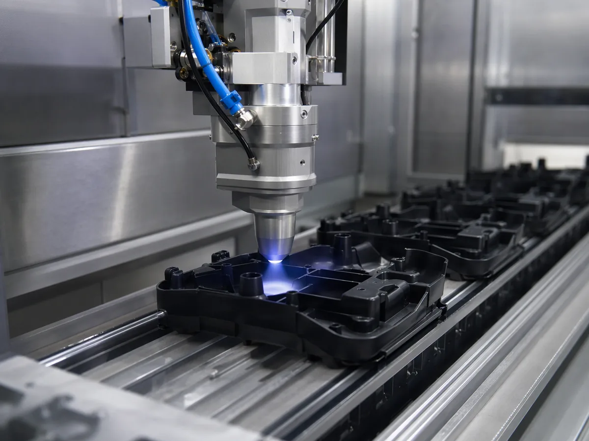 Figure 2: Plasma conditioning of substrates ahead of a second shot. This station exists because wetting is not optional.
How Do You Design a Bond That Survives?
Overmold bond design is the practice of giving the second material geometry to hold onto, thermal conditions to fuse in, and a gate position that does not put the interface where the flow front is coldest. These are the working numbers we start from; treat them as negotiation positions with your own flow analysis, not as laws.
| Fonctionnalité | Working rule | What happens if you skip it |
|---|---|---|
| Through-hole keying | Hole Ø at least 1.0–1.5× the substrate wall; keep the hole’s edge one wall-thickness clear of any part edge | No rivet head forms; peel initiates at the hole and runs |
| Undercut depth | 0.3–0.5 mm on soft elastomers; deeper only if the substrate wall can carry the shear | Undercut becomes a stress riser and the substrate cracks first |
| Edge wrap | Wrap the overmold past the edge onto the return face rather than terminating the layer on a flat | A free edge is a peel starter; fingers find it in week one |
| Wall thickness of overmold | Hold within ±25% across the part; 1.0–2.5 mm is the usual TPE band | Thick sections sink, shrink and pull away from the substrate |
| Gate position | Gate into the substrate-side cavity, not directly onto the future bond face; avoid weld lines across the interface | Weld line through the bond zone becomes the failure path at low force |
| Draft on the second shot | Minimum 1°, more on deep rubber ribs | Ejection stretches the new bond while it is still green |
On shrinkage, the standard compensation formula S = (Lm − Lp) / Lm × 100% still applies to each material separately — but the two materials contract against each other, and that is the part the formula does not tell you. A semi-crystalline substrate and an amorphous overmold will pull in different directions as they cool, which converts a nominal bond into a pre-stressed one. Where the two shrinkage figures differ by more than roughly a factor of two, we argue for mechanical keying before we argue for process tuning.
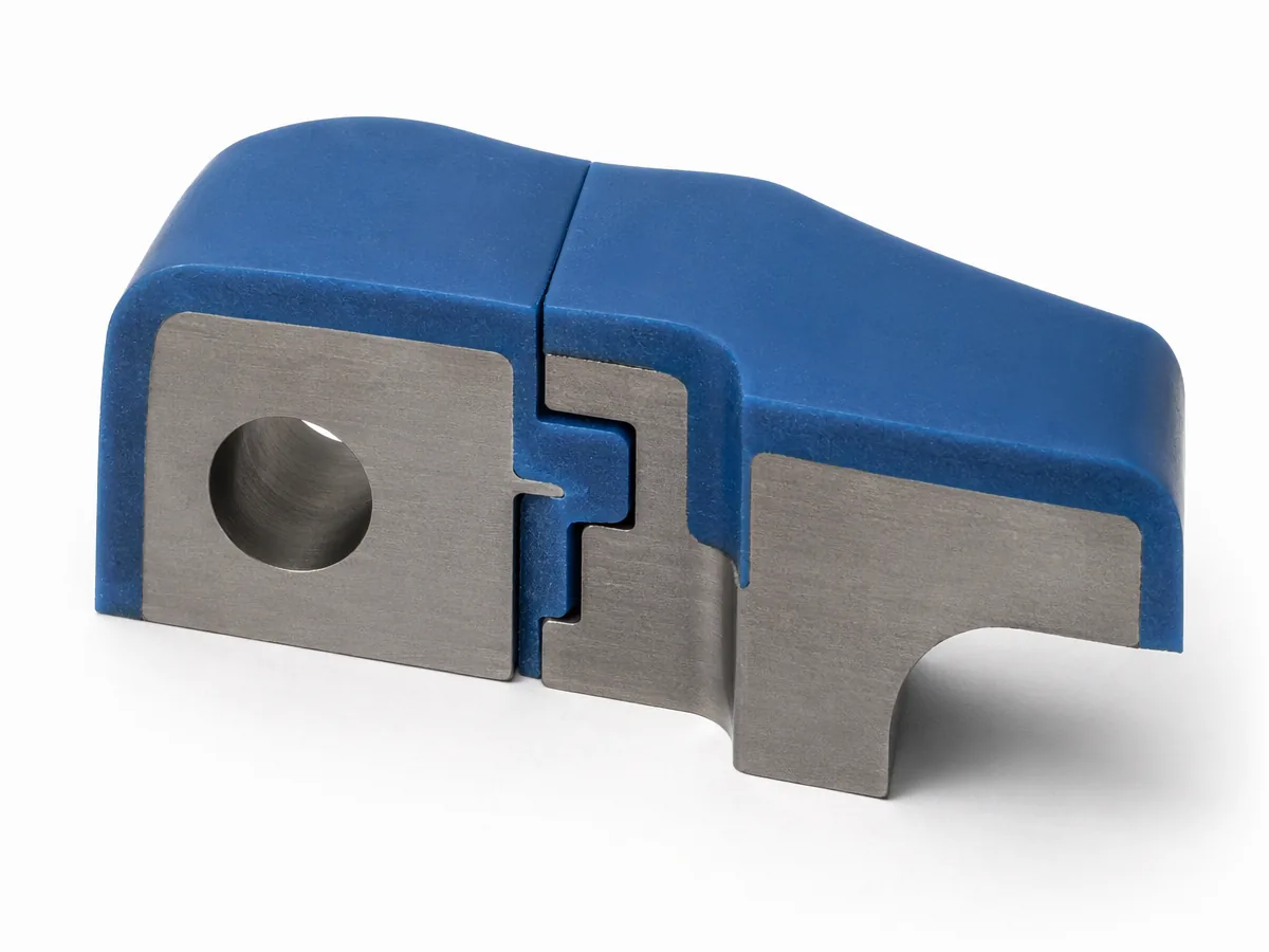 Figure 3: Section through keyed geometry — through-hole rivet plus undercut. This is adhesion you can dimension.
Which Material Pairs Bond Without a Primer?
Overmold compatibility is decided by polarity and melt temperature overlap, not by hardness. The pair must be chemically sympathetic and must both be willing to sit at a shared interface temperature without one of them degrading.
| Substrat | Overmold | Bond class without primer | The thing that kills it |
|---|---|---|---|
| ABS | TPE-S (styrenic), TPU | Good — diffusion plus polar interaction | Regrind-heavy substrate, melted-off gate dust |
| PC | TPU, TPE-S | Good; PC needs high melt temp, so check the elastomer’s thermal ceiling | Elastomer scorching; PC moisture before the second shot |
| PC/ABS | TPE-S, TPU | Bon | Inconsistent blend ratio between lots |
| PA6 / PA66 | PA-based TPE, some TPV | Fair to good; drying is non-negotiable | Absorbed moisture — steam at the interface |
| PP | Standard TPE | Poor — plan on failure | Non-polar, low surface energy on both sides |
| PP | Maleated / PP-based TPE | Adequate to good | Buying the wrong TPE grade because it was cheaper |
| POM, PTFE-filled, silicone-free? | — | Generally no | Very low surface energy; needs flame/plasma plus primer, or a mechanical answer |
| Stainless / aluminium | Silicone, TPU, LSR | Mechanical only, unless primed | Oil film from stamping or machining; anodise sealing residue |
Two notes on that table. First, elastomer selection is really a durometer-versus-melt-temperature argument: a soft 30 Shore A styrenic TPE usually processes cooler than a 80 Shore A one needs, and the hardness you want for grip may sit outside what the substrate tolerates. Confirm with the resin datasheets and our TPE processing guide et TPU guide. Second, “no primer” is a process decision with a cost line attached: primer adds a station, a controlled dry time, and a solvent-handling conversation.
Two-Shot or Pick-and-Place: What Are You Actually Buying?
Two-shot overmolding indexes a still-hot first shot to a second cavity inside one machine — usually on a rotary platen, sliding table or stacked-shot tool. Pick-and-place moves a cooled substrate from one tool to another, by hand or by robot. The bond quality gap between them is real, and so is the money gap.
- Bond quality. Two-shot brings the substrate to the second shot above its softening point, so diffusion has something to work with. A cooled, stored substrate needs surface energy, primer, or keyed geometry to reach the same result.
- Index accuracy. Rotary platen repeatability is what protects your wall thickness around a connector. Drift shows up as one-sided thin wall and local flash, and it is a tooling spec, not a process tune.
- Clamp tonnage. The second shot projects the full cavity area of the overmold plus the shadow of the substrate. Size it on the real projected area, and remember the parting line now runs through a moulded rubber feature instead of clean steel.
- Footprint and cost. A rotary tool is heavier, taller, and costs meaningfully more to build; it also needs a machine that accepts the index unit. Below roughly the tens of thousands, the arithmetic usually sends you to pick-and-place. Above it, labour, reject correlation and bond consistency send you the other way.
- Colour and material changes. Multi-material multi-colour two-shot is where tool cost and purging time both climb; our TPE two-shot design considerations covers the layout decisions.
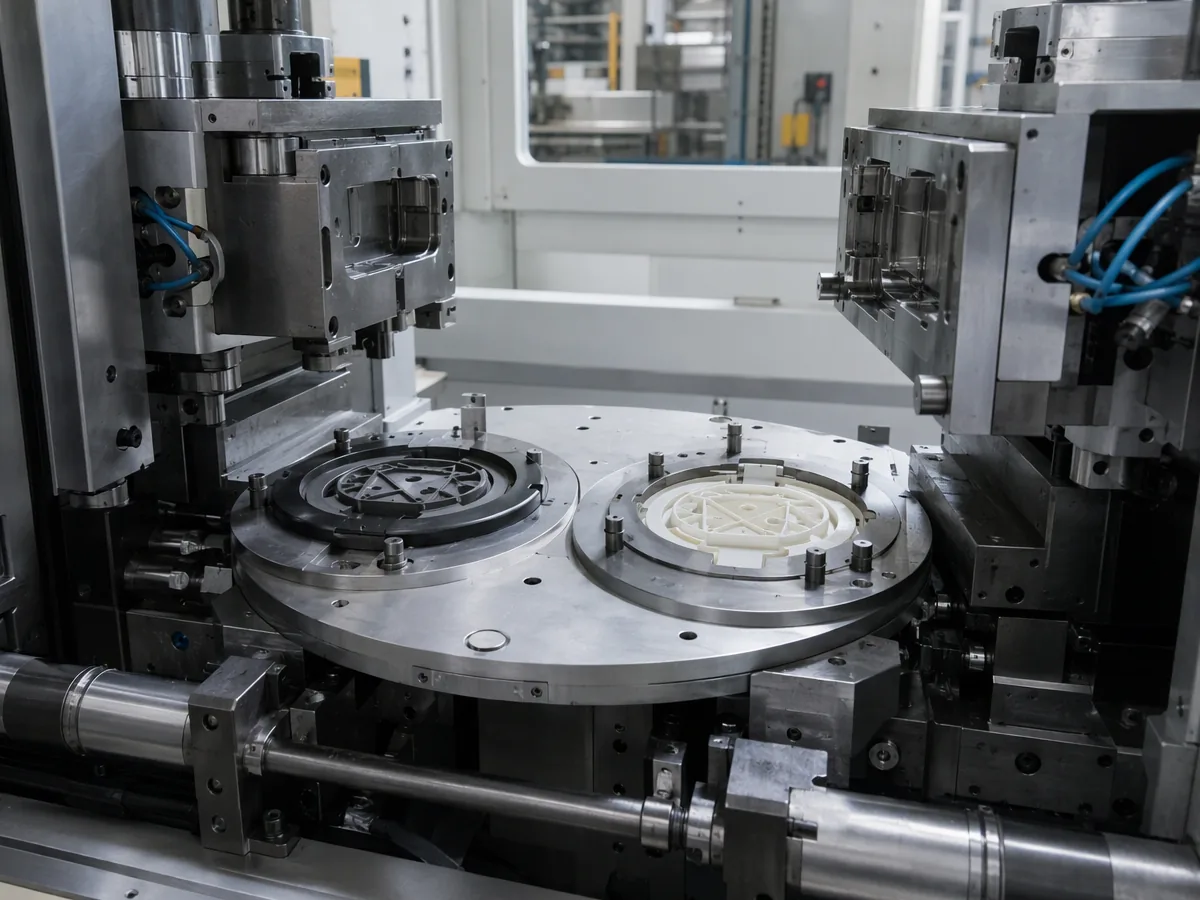 Figure 4: Rotary two-shot index tool. Both cavities visible — first shot left, finished overmold right.
What Overmolding Does to Your Tool
An overmold tool is a two-generation tool: one half makes a part that must survive being handled, stored, sometimes plasma-treated, and clamped again. The wear model is different from single-shot tooling, and quotes that pretend otherwise are quoting half the job.
- Shut-off wear at the second station. Steel now closes onto moulded plastic rather than onto matching steel. Every cycle burnishes that interface, and elastomers with mineral filler abrade it faster. Expect the parting line on the overmold side to be your first cosmetic limit, not your last.
- Venting for outgassing elastomers. Soft TPEs and filled compounds give off volatiles; second-shot cavities are frequently deeper than they look. Vent at the bond-line terminus and at the end of flow, or you will get burnt tips and a weak interface in the same location.
- Thermal split across one tool. Substrate-side and overmold-side want different steel temperatures. That is two water circuits, possibly a temperature controller per side, and a plate design decision — settled before steel, expensive after.
- Gate and runner erosion. Ablasive elastomer compounds plus high shear at a small gate equals a gate that widens. A gate that widens changes fill balance cavity to cavity, which changes cosmetic look, which you will blame on the resin.
- Corrosion from conditioning. Flame and plasma treatment, and some primers, are hard on polished steel and on the release coating you applied to help ejection. If the substrate is being conditioned, the substrate tool’s finish spec is part of the argument.
These are the reasons our free DFM on an overmolded part looks at handling, storage and conditioning between shots, not just wall thickness. The hidden tooling risks are catalogued in our overmolding flash and bonding-failure analysis.
How Do You Prove the Bond Before Production?
An overmold is qualified by destructive and environmental evidence on the real geometry, from the real tool, with cavities identified. A supplier who cannot produce four artefacts below is telling you they hope.
- Peel or destructive test with a stated method. Report the method and the units (peel force per unit width, or percentage substrate failure after tearing). “Strong adhesion” is not a result. Substrate cohesive failure — rubber left on the plastic, plastic torn — is the pass condition people forget to specify.
- Thermal cycling on the assembly. Different shrinkage and CTE between two materials is a pump. Cycle it and look for the ring forming at the edge, because that is where the first field return will start.
- Sealing verification, if the overmold is a seal. IP ratings are defined by IEC 60529 test methods on the finished geometry, not by the presence of rubber.
- Cavity-level evidence. Adhesion is a process-window result; the cavity that ran cold will bond worse than the cavity that ran hot. Samples and reports identified by cavity, not averaged — the discipline in our T1 evidence package guide.
Then write it down before the volume: acceptance criteria, sampling frequency, and what happens when a lot fails belong in the quality agreement, not in the reply to the first complaint.
The Ideal Pro Path From Drawing to Overmoulded Production
- Quote with the interface argument (24 hours, free DFM and mould-flow). We state the bond mechanism we are relying on and what it costs. If we are relying on wetting alone, we say so here.
- Material pair confirmed on datasheets, then trialled. Substrate grade, overmold grade, durometer, primer decision — then a trial shot on the real pair before the production tool is committed.
- Tool built as a two-generation tool. Shut-offs, venting, split thermal circuits, and a service plan for the overmold-side parting line and gates.
- T1 in 5–10 days on straightforward tools (10–20 on complex), as an evidence package. Cavity-labelled samples, actual machine values, tool state.
- Bond verification. Peel with method stated, thermal cycling, IP check where the part seals, per-cavity results.
- Ramp with the interface controlled. Substrate handling, storage time and any conditioning step are process parameters under change control, because they are where the nine-day silicone film crept in.
No minimum order, one accountable team from mould design through finishing, presses up to 1,600 tons, 99.8 percent on-time across the shop.
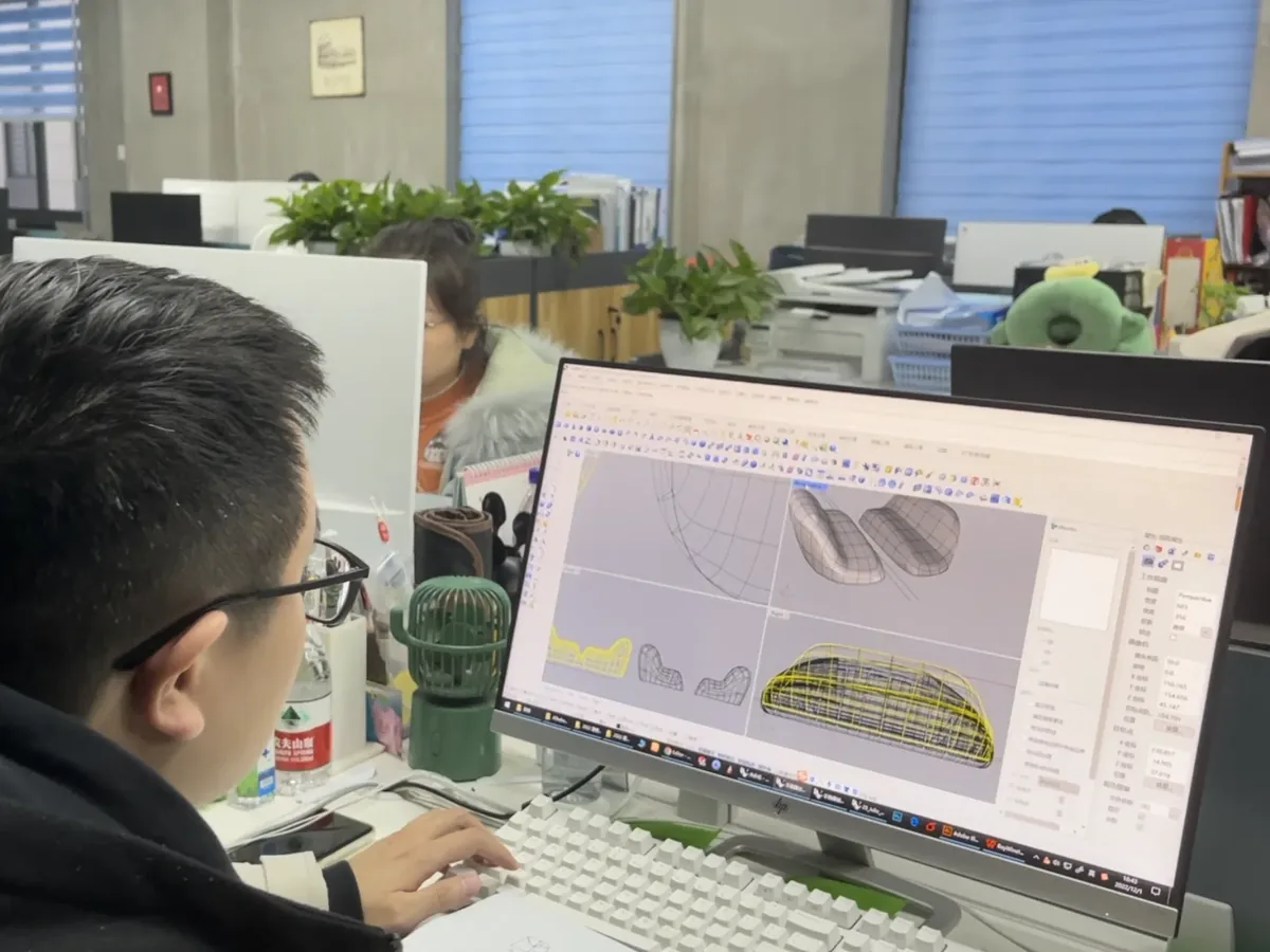 Figure 5: Bond design gets settled here, on the model, before any steel exists.
When Overmolding Is the Wrong Call
We would rather lose the quote than the customer. Do not overmould when the two materials have no shared thermal window and no mechanical answer — you will buy a permanent reject rate. Do not overmould for a serviceable product: an overmold cannot be disassembled, and if your warranty model needs the rubber replaced, design a gasket. Do not overmould a PP substrate with a standard TPE because a datasheet called them “compatible”. And do not look for this at Ideal Pro if you need IATF 16949 automotive safety parts or implant-class medical device routes: we run ISO 9001:2015 with RoHS and FCC documentation, and those two certification ladders belong to specialists who live inside their audit worlds. Ask us anyway for the free DFM; the interface opinion is useful whoever cuts the steel.
Résumé
Overmolding is a forming process whose entire risk sits on a plane you cannot see after the mould opens. Four mechanisms make adhesion, and only mechanical interlock is fully specified by your drawing — so design keying, wrap edges past the free boundary, keep the interface out of weld-line territory, and treat substrate surface energy as a process parameter with a clock on it. Choose two-shot when volume and bond consistency justify the tool; choose pick-and-place when cash and flexibility do. Then prove the bond with a stated peel method, thermal cycling, real IP verification and cavity-identified evidence, and put the acceptance criteria in the quality agreement while everyone is still friendly.
📞 Tel/WhatsApp: +86 156 0682 1288 · 📧 [email protected] · 🌐 ideal-pro.com
Sources
- IEC 60529 — degrees of protection provided by enclosures (IP code): the test basis for any overmould claimed as a seal.
- ASTM D903 — peel strength of adhesives by 180-degree method, and ASTM D2240 for Shore hardness: the two test languages an adhesion claim should be written in.
- ASTM D1238 — melt flow index: the number that decides whether two melts will actually diffuse across an interface.
- ISO 9001:2015 — the documented quality framework these practices sit inside at Ideal Pro.
- Ideal Pro published shop standards on ideal-pro.com: 24-hour quote with free DFM and mould-flow, T1 in 5–10 days on straightforward tooling, presses up to 1,600 tons, over 1,000 mould sets per year, 99.8 percent on-time delivery.
- All arithmetic here runs on stated assumptions. Treat ranges as planning inputs to argue with, not as your quote.
Is overmolding the same as insert molding?
No, and the difference is expensive. Insert molding moulds plastic around a pre-made insert — normally metal — whose job is to survive pull-out and torque. Overmolding is the broader category: a second moulded material on a substrate that is very often itself moulded plastic, whose job is to survive peeling. Every insert moulding job is technically overmolding; most overmolding jobs are not insert moulding, and quoting one tool where the geometry needs a locating second station is how that confusion shows up on your invoice.
Why does my TPE peel off a PP substrate even though the supplier says they bond?
Because both materials are non-polar and low surface energy, so there is nothing for the melt to wet and nothing to diffuse across. “Bondable” grades exist — maleated PP and PP-based TPE compounds — and they work, but they are a specific purchase decision, not a default. If you are locked into a commodity PP substrate, budget for primer or plasma plus a tie-layer, or design mechanical keying hard enough that chemistry stops being the load path.
Two-shot or pick-and-place: how do I decide without guessing?
Three questions. Can both materials sit at a shared interface temperature without scorching the elastomer — if not, two-shot buys you little. Is your annual volume high enough that the rotary tool’s extra cost per part falls below the labour and reject correlation of manual loading — usually a tens-of-thousands threshold, and it moves with your part. Do you need the second material on a face that a robot or a hand can locate repeatably — if the datum is soft or flexed, index it in the tool instead of in the fixture.
What is a realistic overmold wall thickness, and what goes wrong outside it?
For soft TPE the practical band is roughly 1.0–2.5 mm, held within about ±25% across the part. Below that you get short shots and torn edges during demould; above it you get sink, extended cycle, and a thick section that shrinks away from the substrate and pre-stresses the bond you were relying on. Where a grip genuinely needs more than that, we convert the mass into cored ribs or a lower-durometer grade rather than simply thickening it.
How do I specify adhesion in a drawing or purchase order so it actually binds the supplier?
Name the method, the units, and the failure mode you want. For example: peel per ASTM D903 on the as-moulded assembly from the production tool, minimum value agreed at T1, with acceptance requiring substrate cohesive failure rather than clean adhesive separation, tested after a defined thermal-cycle count. Then require cavity identification on the samples. If the specification does not name a destructive method and a post-environment condition, it cannot fail a part and it should not be called a requirement.
À propos de l'auteur

Alex Yu
Ideal Pro Manufacturing
Alex est le cofondateur d’Ideal Pro, mais lorsqu’il ne supervise pas des projets clés ou ne dirige pas l’équipe technique, vous le trouverez sans doute en train de faire une longue balade à vélo, à la recherche du meilleur café de la ville, ou en train de planifier sa prochaine aventure de voyage. Fort de plus de 20 ans d’expérience dans le commerce international et la gestion de projets, il a tout vu : délais serrés, problèmes techniques complexes et tout ce qui se trouve entre les deux. Il est convaincu qu’un travail de qualité naît d’un esprit bien reposé et d’une bonne tasse de café, et il apporte cette même curiosité et ce même souci du détail à chaque projet qu’il entreprend. Lorsqu’il n’est pas au bureau, il se trouve généralement en plein air, à explorer de nouveaux endroits et à glaner des anecdotes à partager.
 English
 French
 Dutch
 German
 Japanese
 Korean