Introduction to Injection Mold Structure
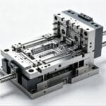
An injection mold is primarily composed of two halves: the moule mobile (connected to the moving platen of the injection molding machine) and the fixed mold (connected to the fixed platen). During the injection molding process1, these two halves close to form the gating system and the mold cavity. When the cycle is complete, the mold opens, separating the moving and fixed halves to allow for the ejection of the plastic part.
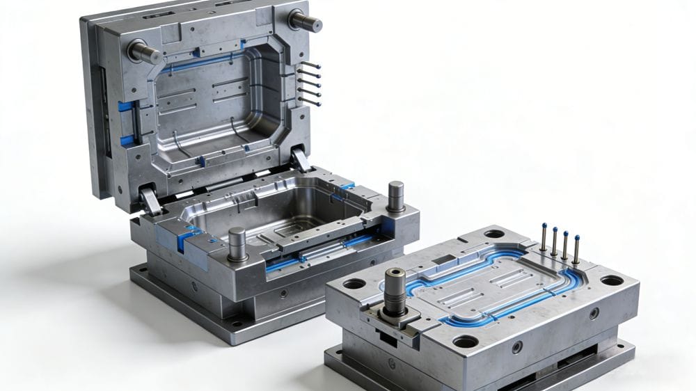
While mold structures can vary significantly depending on the plastic material, part geometry, and machine type, the basic architecture remains consistent. A standard mold consists of four main systems:
- The Gating System: The flow channels for the plastic melt.
- The Temperature Control System: Cooling or heating channels.
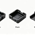
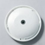
- The Molding Parts: The components that define the part's shape (cavity and core).
- The Structural Parts: Guide pins, ejection systems, and support plates.
Note : The gating system and molding parts are in direct contact with the plastic. Consequently, they are the most complex components, requiring the highest precision and surface finish.
1. The Gating System
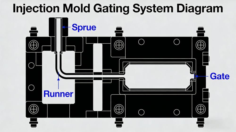
The gating system, often called the runner system, is the network of channels that guides the molten plastic from the injection machine nozzle into the mold cavity. Its design directly dictates the quality and production efficiency.
The Sprue The sprue is the primary channel connecting the injection machine nozzle to the runner or cavity.
- Design: The top of the sprue is concave to seat the nozzle properly.
- Dimensions: The inlet diameter should be slightly larger than the nozzle diameter (typically by about 0.8mm) to prevent overflow and blockage. The standard diameter ranges from 4mm to 8mm.
- Taper: The sprue usually tapers inward at an angle of 3° to 5° to facilitate the removal of the sprue puller.
The Cold Slug Well Located at the end of the sprue, this is a small void designed to capture the "cold slug"—the solidified plastic that forms at the nozzle tip between shots.
- Function: If this cold material enters the cavity, it can cause internal stress or surface defects.
- Ejection: The bottom often features an ejector pin with a zigzag or hooked tip (Z-pin) to pull the solidified sprue out during mold opening.
The Runner In multi-cavity molds, the runner connects the sprue to the individual cavities.
- Balance: Runners should be arranged symmetrically and equidistantly to ensure the melt fills all cavities at the same speed.
- Cross-Section: While a circular cross-section offers the lowest flow resistance, it is difficult to machine (requiring alignment on both mold halves). Therefore, trapezoidal ou semi-circular cross-sections are commonly used.
- Surface Finish: The runner surface must be polished to reduce flow resistance and increase filling speed.
The Gate The gate is the final, smallest opening connecting the runner to the cavity.
- Function: It controls flow speed, prevents backflow (by cooling rapidly), and generates shear heat to lower viscosity. Crucially, it allows for easy separation of the part from the runner system.
- Design: Gates are typically rectangular or circular. They should be small in cross-section and short in length.
- Placement: Gates are usually located at the thickest part of the product to ensure proper packing, in areas that do not affect the aesthetic appearance.
Conseil : When designing gates, consider the specific viscosity of the plastic melt. A smaller gate is generally preferred as it is easier to enlarge later if filling issues occur.
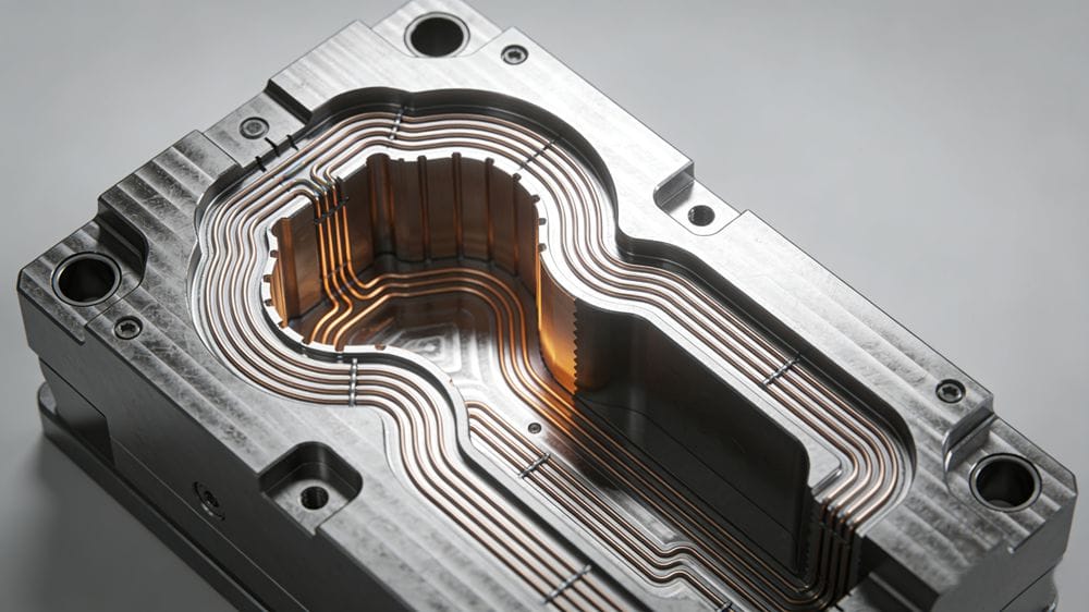
2. The Temperature Control System
To meet the strict requirements of the injection molding process, a temperature control system2 is essential. For thermoplastics, this is primarily a système de refroidissement.
- Cooling Channels: The most common method involves drilling water channels throughout the mold. Circulating cooling water extracts heat from the mold, solidifying the plastic part.
- Heating: In some cases, hot water, steam, or electric heating rods are installed to maintain high mold temperatures for specific engineering plastics.
3. Molding Parts
Les molding parts3 are the "heart" of the mold, defining the geometry of the final product.
- The Cavity: Forms the external shape of the product.
- The Core: Forms the internal shape (such as holes or slots).
Design Considerations
- Material Selection: These parts must withstand high injection pressure. They are typically made from hardened, corrosion-resistant steel.
- Surface Finish: To ensure the part releases easily and looks good, surfaces in contact with plastic usually require a surface roughness of Ra > 0.32µm.
The Vent As molten plastic fills the cavity, it displaces air. If this air cannot escape, it causes defects like air pockets, short shots, or burn marks (dieseling).
- Location: Vents are placed at the end of the flow path or on the parting surface.
- Dimensions: On the parting surface, these are shallow slots, typically 0.03–0.2mm deep et 1.5–6mm wide.
- Safety: Vent locations should never face the operator to prevent molten plastic from spraying out accidentally.
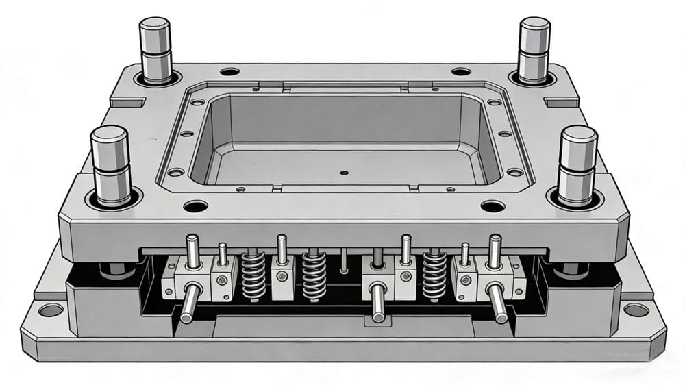
4. Structural Components
These parts provide the mechanical framework and functionality of the mold.
Guiding Mechanism To ensure the moving and fixed mold4s align perfectly during closing, guiding components are mandatory.
- Components: Typically consists of four sets of guide pins et bushings.
- Auxiliary Locks: Sometimes, internal and external tapered surfaces are added for precise locking.
Ejection System This mechanism pushes the finished part and the runner system out of the mold.
- Components: Includes the ejector plate, ejector pins, and a return pin (which pushes the ejector plate back into position when the mold closes).
Side-Action (Core Pulling) Mechanism For parts with side holes or undercuts, the part cannot be ejected straight out.
- Function: A side-action mechanism (often using angle pins or hydraulic cylinders) pulls the side cores outward before the main ejection takes place.
Standard Mold Base To reduce design time and manufacturing costs, most injection molds utilize a standard mold base (such as DME or HASCO standards), which includes the support plates, clamping plates, and leader pins.
Explore this resource to gain a comprehensive understanding of the injection molding process, its stages, and best practices. ↩
Discover the significance of temperature control in ensuring optimal molding conditions. ↩
Understanding molding parts is crucial for grasping how final product shapes are achieved. ↩
Exploring the fixed mold's function will provide insights into the overall injection molding mechanism. ↩