

The medical sensor on your wrist, the hearing aid in your ear, the camera module in your phone — all of them are shrinking, and the plastic parts inside them are forced to follow. That trend has pushed injection molding into a regime where the rules that work for a 150-gram bumper housing stop applying: cavities get thinner than a hair, pressure requirements climb into the thousands of bars, and a 20-micron error in the gate changes filling pressure by a percentage point that matters.
Micro injection molding is the specialized discipline for making plastic parts that are small in weight, thin in section, and fine in feature — typically under one gram, with features below one millimeter and tolerances in single-digit microns. This guide covers what micro molding actually involves: the physics that make it different, the design rules that protect your tooling investment, how the molds are made, the machines and process parameters, material selection, quality systems, cost, and the questions to ask before you commit a part to a supplier.
Unter Ideal Pro, we build precision injection molded parts for medical, electronics, and optics customers. Most of the failures we see trace back to design and process fundamentals, so everything below is written from that vantage point.
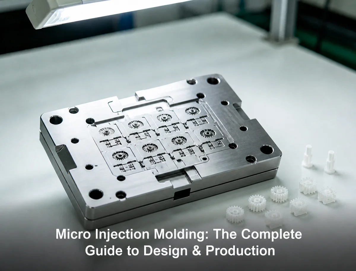
What Is Micro Injection Molding?
Micro injection molding is the mass production of thermoplastic parts whose dimensions, wall sections, and feature sizes fall below the range where conventional molding can repeat quality reliably. As an intuitive scale reference, a grain of rice weighs about 30 mg, and many micro parts are lighter than that; features in the 10–100 µm band sit in the region where conventional rules of thumb stop predicting how a material will behave. There is no single industry standard that draws the line, but in practice most shops converge on a working threshold:
| Parameter | Conventional injection molding | Micro injection molding |
|---|---|---|
| Part weight | Typically above 1 g | 0.01–1 g |
| Feature size | Above 1 mm | Below 1 mm, down to roughly 100 µm |
| Wandstärke | 0.5–4 mm | 0.05–0.5 mm |
| Typical tolerance | ±0.05–0.1 mm | ±1–5 µm on critical dimensions |
| Machine clamp force | 50–2,000 t | 5–50 t |
| Screw diameter | 20–80 mm | 5–20 mm |
| Zykluszeit | 20–60 s | 5–20 s |
The last row is easy to underestimate: thin sections cool in seconds, so a micro part often cycles faster than a part ten times its size. That speed is one of the hidden cost advantages of the process.
Where “micro” ends and “conventional” begins is fuzzy, and that is fine. What matters is which physics are in control. If your part’s quality is dominated by thin-wall flow, rapid cooling, and micron-level mold accuracy, you are in micro territory — even if the part weighs three grams.
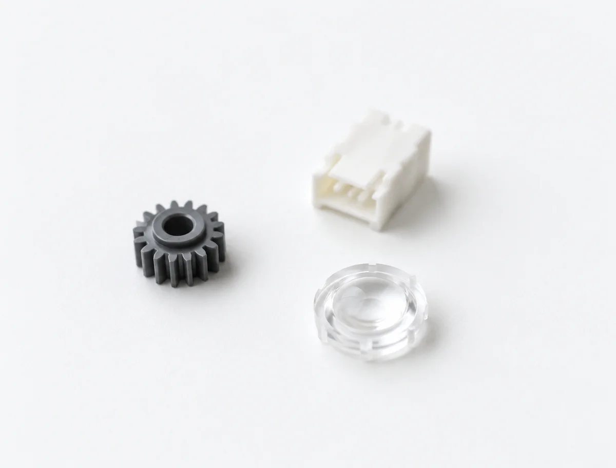
Why Scale Changes the Physics: Micro vs. Conventional Molding
Micro molding is not simply smaller molding. Four physical effects flip at small scale:
Flow resistance explodes. Pressure drop across a thin channel scales roughly with the inverse cube of its thickness (ΔP ≈ 12μLQ / wh³). Halve the wall thickness and you need roughly eight times the pressure to push the same melt through the same distance. This is why micro molding commonly runs at 1,000–2,000 bar — not because the melt is hard to pump, but because the cavity it must fill is extremely restrictive.
Cooling owns the cycle. In a 3 mm wall, heat leaves slowly and holding pressure dominates the cycle. In a 0.3 mm wall, the section freezes in one to three seconds. The process becomes a filling problem: there is a narrow window between “too slow and the part freezes short” and “too fast and shear heat degrades the melt.”
Ejection forces must shrink. A 200-gram part tolerates a firm eject. A 0.4-gram part with 0.2 mm ribs will crack under the same force. Micro ejection uses fine-pitch pins, uniform lifters, and often air blowing, tuned part by part.
Small errors become big effects. A 20 µm change in gate depth, a 5 µm misalignment between mold halves, or a few degrees of melt temperature drift that a conventional part would shrug off will shift a micro part’s fill pattern, weld line position, or final dimension. The whole system — machine, mold, material — must be specified to micron-level accuracy before the first shot.
Industries That Rely on Micro Injection Molding
Demand for micro parts concentrates in a few industries where miniaturization is a product requirement rather than an option:
| Industry | Typical micro parts | Critical specification |
|---|---|---|
| Medical devices | Sensor housings, microfluidic chips, syringe components, needle hubs, implant components | Biocompatibility, ISO 13485, dimensional stability |
| Electronics and MEMS | Connectors, socket contacts, package frames, antenna housings | Insertion force, insulation, warpage |
| Micro-optics | Plastic lenses, prisms, light guides, waveguide housings | Surface accuracy, clarity, replication |
| Automobilindustrie | Sensor housings, fuel system components, micro gears, retainers | Heat and vibration resistance, IATF 16949 |
| Aerospace and defense | Lightweight fasteners, brackets, connector components | Strength-to-weight, dimensional repeatability |
| Lab-on-chip | Channels, chambers, interfaces | Channel fidelity, sealing |
| Dental | Bracket components, aligner hardware | Fit, biocompatibility |
| Consumer devices | Hearing aid shells, earbud components, watch parts | Tolerance, surface finish |
Medical is the anchor market. Microfluidic channels under 500 µm, syringe tips, and diagnostic sensor housings all live at the edge of what mass production molding can do, and the regulatory bar — USP Class VI biocompatibility, ISO 13485 process validation — selects for suppliers who can document the entire process. When your part is medical, validation requirements shape design choices as much as geometry does; our breakdown of what ISO 13485 actually changes in a molding program is a useful companion read: medical injection molding vs. standard: ISO 13485 and cleanroom validation.
Electronics and optics are the growth engines. MEMS packages and camera lenses are the two product classes where both part count per device and miniaturization pressure are rising at the same time.
Designing for Micro Molding: DFM Rules That Matter
Most failed micro molds fail in the CAD file, not on the shop floor. A part that looks fine on screen can be impossible to mold, impossible to eject, or impossible to inspect. These are the rules we hold customers to in a DFM review:
1. Use the thickest wall that still functions. Because ΔP scales with 1/h³, every 0.05 mm of unnecessary thinness multiplies the pressure required. For most micro parts the practical band is 0.1–0.4 mm, and uniform thickness matters more than absolute thickness — uneven walls cool unevenly and warp.
2. Respect aspect ratios. A rib taller than roughly 3× its thickness will short-shot or sink; a hole smaller than about 0.2 mm is hard to keep free of flash and harder to inspect. If a feature is at the edge of what the process can do, ask whether a secondary operation — laser drilling, ultrasonic welding — is cheaper than fighting the mold.
3. Add draft even when the part is tiny. 0.5–2° of draft on all pulled surfaces is non-negotiable: at micro scale the surface contact area is large relative to part mass, and sticking is the dominant ejection failure mode. The upside is that micro parts can sit at the low end of that band — shorter draw depths and smaller shrinkage forces on thin walls need less draft than large parts. Zero draft is still a trap.
4. Size corners generously. Internal radii below 0.1× wall thickness concentrate flow, stress, and mold wear. For a 0.2 mm wall, keep internal corners at 0.05 mm or larger where possible.
5. Gate small, deliberately. Gates of 0.1–0.5 mm control filling at micro scale, and gate position sets the fill pattern, weld lines, and molecular orientation. For optical or appearance parts, valve gates or pin gates on non-critical surfaces are standard.
6. Vent for the volume, not the area. Trapped gas in a 0.15 mm section causes short shots and burn marks. Parting line vents of 0.01–0.03 mm thickness, or laser-drilled vent pins in the core, are typical. On a micro mold the vent land can be only a few microns deep — deep enough for air to escape, shallow enough that melt cannot flash through.
7. Allocate tolerances by function. Hold ±1–5 µm only on the dimensions the assembly actually requires. Putting ±3 µm on a non-critical hole triples tooling and inspection cost with no functional benefit.
8. Design for measurement. If a critical feature cannot be measured with a CMM probe or a vision system, the tolerance is a wish, not a specification. Metrology belongs in the DFM, not after the mold is cut.
9. Keep it elegantly simple. Every new feature, undercut, or wall-thickness change multiplies variation risk. The most successful micro parts are simple in a way that can feel almost under-designed.
Our thin-wall injection molding guide covers the wall thickness and flow mechanics in more depth — the two topics where most micro part design errors originate.
How Micro Molds Are Made
A micro mold is a precision instrument that happens to make plastic parts. The cavity tolerances are tighter than the part tolerances they must hold, and the manufacturing route reflects that:
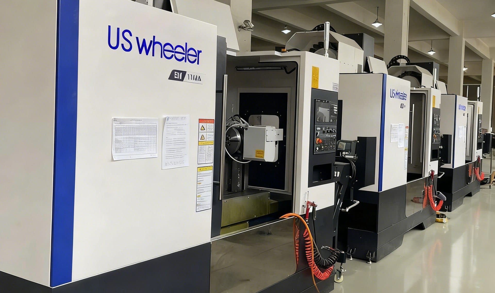
Base steel and hardening. Micro molds use premium pre-hardened or through-hardened steels: NAK80 for general work, SKD11 for high-wear features, and 1.2344 (S136) where corrosion resistance matters. Engineering polymers such as PEEK, PPSU, and PPA are corrosive to standard tool steel at molding temperatures, and a pitted cavity will scar every optical surface it touches. Typical hardness after treatment is 45–55 HRC.
Micro CNC milling handles large geometries to ±5–10 µm and sets up features for electrical work.
Sinker (conventional) EDM is the workhorse for small cavities, pockets, and deep thin features a cutting tool cannot reach. Electrode wear must be accounted for in the program — on a 0.3 mm rib, even a few microns of offset matters.
Wire EDM cuts through features: thin slits, through-holes as small as 0.1 mm, and complex through-geometry. Wires of 0.05–0.15 mm are common in micro work.
Precision grinding and lapping bring critical surfaces to final accuracy. Femtosecond laser machining has entered the mix for features and vent channels that neither a cutting tool nor a wire can reach.
Diamond turning is reserved for optical cavities: aspheric lenses, prisms, and light guides are machined in diamond or carbide tooling to surface accuracy well under 1 µm, then polished to Ra ≈ 0.03 µm (SPI A-1) so light passes without scattering.
Cavity count and cooling. Micro molds run 8 to 128+ cavities. Because cycle time is short, multi-cavity is the main lever on unit cost. Conformal (manifolded) cooling is increasingly common to prevent differential cooling of 0.2 mm sections — the primary driver of warpage.
Before release, the mold itself is inspected: CMM for critical cavity dimensions, optical or laser scanning for surface integrity. The mold is a fixture, and it is treated like one.
Machines and Process Parameters
The machine has to match the process, or the process has to shrink to fit the machine. Dedicated micro presses are built for small shot volume and fine control:
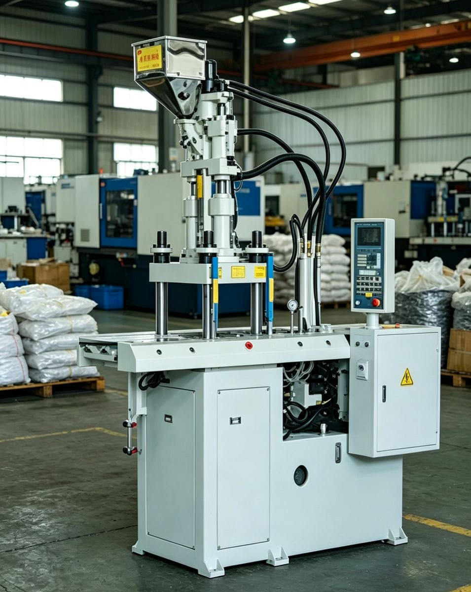
- Screw diameter 5–20 mm, shot size in grams
- Clamp force 5–50 t, with platen sizes matched to compact molds
- Injection pressure to 1,000–2,000 bar
- High-resolution servo drives on injection, clamp, and ejection — repeatability is the whole game; on a micro tool, even a micron of clamp misalignment can produce flash
- Shot volumes below 0.1 cm³, with plunger or micro-screw designs that cut melt residence time and shear degradation
- Small nozzles (2–6 mm) to minimize dead volume and melt residence
- Vision-assisted handling — parts this small are frequently removed, inspected in-line, and assembled by robot rather than by hand
Running a part on a retrofitted conventional machine is possible for looser specs, but a servo-clamp with micron-level positioning error will not hold ±2 µm shot to shot. Match the machine class to the tolerance you are promising.
Typical processing windows (always confirm against the resin’s datasheet):
| Material | Melt temperature (°C) | Mold temperature (°C) | Anmerkungen |
|---|---|---|---|
| PP | 200–240 | 30–60 | Fast flow, low cost |
| PBT | 240–260 | 40–80 | Electrical grades |
| PA12 / PA66 | 260–290 | 40–100 | Drying mandatory |
| PC | 280–320 | 60–120 | High viscosity, shear sensitive |
| LCP | 300–340 | 50–100 | Ultra-low viscosity, low shrinkage |
| PPSU | 330–360 | 60–100 | High drying temperature |
| PEEK | 370–410 | 80–140 | Corrosion-resistant barrel and nozzle required |
Three process points matter more at micro scale than any single number:
1. Injection speed is the primary fill control. Thin sections need fast, controlled velocity before the melt front freezes; pressure alone cannot save a slow fill.
2. Holding must be brief and light. Over-holding into a frozen part is how you create sink and internal stress in 0.2 mm walls.
3. The window is narrow — monitor it. In-mold pressure, melt temperature, and servo energy are tracked on SPC charts; the factors that affect precision injection molding are covered in detail. A process that “works” on day one but drifts on day nine is not a validated process.
Process development for a new micro part typically runs a Design of Experiments pass — melt temperature, injection speed, holding, mold temperature — to find the stable region, then a PPAP-style validation to prove it holds across 3,000+ consecutive shots.
Material Selection for Micro Parts
Flow is the first criterion. A resin that fills a 3 mm wall with effort may not fill a 0.2 mm channel at all — melt flow index (MFI ≥ 20 g/10 min) and low processing viscosity outrank most mechanical properties at micro scale. The mechanical question then becomes: of the resins that flow, which survives the service?
| Resin | Why it is used in micro | Typical micro application | Watch out for |
|---|---|---|---|
| PEEK | Heat, chemical, mechanical; implant grade | Sensor housings, implant components | 370–410 °C processing; corrosion-resistant steel; cost |
| LCP | Lowest viscosity, near-zero shrinkage | RF/antenna parts, connectors, thin walls | Crystallization control for optics |
| PPSU | Toughness plus clarity; autoclave and gamma stable | Lab, diagnostics, fluidics parts | Drying (120 °C for 4 h or more); cost |
| PPS | Heat and chemical resistance | Engine bay sensor parts | Glass filler abrades tooling |
| PA12 / PA66 | Toughness, wear | Micro gears, flex features | Drying mandatory; high shrinkage |
| PC | Clarity, toughness | Optical housings, lens mounts | Shear sensitivity; high melt pressure |
| PBT | Electrical, dimensional | Connectors, terminals | Moderate flow; crystalline shrinkage |
| PP | Cost, flow, biocompatible grades | Consumables, syringe components | High shrinkage; warpage control |
Two operational notes. First, hygroscopic resins (PA, PEEK, PPSU) must be dried to under 0.02% moisture before molding — at micro scale a single water-induced vapor pocket in a 0.3 mm channel is a rejected part. Second, for appearance or optical parts, color and masterbatch consistency between lots is a quality requirement, not a cosmetic one. Third, for single-use medical devices, specialty biocompatible grades of polyethylene and polycarbonate engineered for patient contact form their own category — select them for safety class first, flow data second.
Quality Control: How Micro Parts Get Verified
At micro scale, inspection is an uncertainty-budget problem: if the tolerance is ±3 µm, the measurement system itself must be stable to a fraction of that. A 20 µm feature is beyond calipers and beyond an optical comparator — the measuring instrument is part of the design, not an afterthought. A measurement system analysis (MSA) on the gauges is a prerequisite, not an extra.
Contact CMM remains the reference for dimensional sign-off, probing critical features with 1–2 µm probe tips. Vision and optical systems handle 100% in-line inspection of features a CMM probe would damage — thin ribs, micro holes, weld line locations. Laser confocal or structured-light scanning is used for aspheric and optical surface verification. Scanning electron microscopy and micro-CT come in for surface topography and internal void structure that optical methods cannot reach. X-ray appears where internal porosity or fiber orientation matters.
On the process side, the control stack is:
- SPC on every critical dimension, with Cpk ≥ 1.33 as the floor and 1.67 as the target
- In-mold pressure and melt temperature trending to catch drift before parts drift
- First article inspection at the start of every production run
- PPAP Level 3 documentation for automotive and medical programs
- Material CoA/CoC traceability to the lot, plus process parameter logs with the batch
Certifications frame the system: ISO 9001 as baseline, ISO 13485 for medical, IATF 16949 for automotive. For micro parts, the difference between a credible supplier and a marketing phrase is the documentation trail: when a customer asks which shot range a Cpk was calculated from, and what the mold temperature was during it, a good shop answers in minutes.
Cost and Volume: When Micro Molding Makes Sense
The economics look odd at first: expensive tooling, but a potentially low unit price.
Tooling. A single-cavity hardened micro mold with micro-EDM and wire work typically lands between US$10k and US$30k; multi-cavity (16–64+), optical-grade, or very high-cavity molds push toward $30k–60k and beyond. The premium over a standard mold of comparable size is the micro-machining and inspection content, not the steel.
Unit cost. Cycle times of 5–20 seconds, cavity counts in the tens, part weights in milligrams, and minimal secondary operations mean high-volume unit prices can reach a few cents per part even for complex geometry. Cavity count is the biggest lever: doubling cavities roughly halves unit cost, at a multiple of the tooling cost.
The volume threshold. Below roughly 10,000–50,000 parts per year, the tooling investment rarely pays back and competing routes win:
| Route | Sweet spot | Anmerkungen |
|---|---|---|
| Micro injection molding | 10k–10M+ parts per year | Best cost and consistency at volume |
| Micro 3D printing (SLA / SLS, two-photon) | Prototype to a few thousand | No tooling; two-photon handles unmoldable lattice structures, with surface-finish and engineering-material limits |
| Micro CNC / wire cutting | Prototype, small batches | Per-part cost stays high |
| LOM (lithography + molding) | Ultra-thin, ultra-complex, mid volume | Niche; limited material set |
Other cost movers: material (PEEK resin costs tens of times more per kilogram than PP, but milligram quantities mean cycle time dominates), surface finish requirements, inspection level (100% optical vs. sampling), and first-pass yield — a part running at 99.5% yield is materially cheaper than one requiring rework.
Common Micro Molding Defects and How to Fix Them
The defect set overlaps with conventional molding, but every failure mode arrives earlier and looks worse at micro scale:
| Defect | Usual cause | Fix direction |
|---|---|---|
| Short shot | Fill pressure or velocity too low; venting blocked; melt freezes early | Raise injection speed, check vent paths, re-verify gate size |
| Flash | Parting line misalignment; over-holding; mold wear — a few-micron burr can jam a microfluidic channel | Re-align halves, trim holding pressure, inspect for wear |
| Weld line | Multiple-gate fill pattern; melt temperature low | Change gate layout, raise temperature, vent at the weld |
| Sink / voids | Uneven cooling; over-holding | Even out wall thickness, shorten hold, adjust mold temperature |
| Ejection damage | Sticking; insufficient pin coverage; sharp ribs | Lifters plus air blowing, add pin coverage, add draft |
| Discoloration / degradation | Excessive shear or residence time | Lower melt temperature, reduce back pressure, shorten cycle |
| Dimensional drift | Melt or mold temperature instability; shrinkage | Tighten temperature control, SPC with in-mold feedback |
| Contamination / specks | Moisture, old material, hopper contamination | Dry resin, purge, clean hopper and feeder |
Two meta-points. First, defects at micro scale are almost always system problems, not single-parameter problems: gate, vent, and holding pressure interact, and short shots and flash are born at that interface — fix in that order. Second, yield data from the validation run is a contract-level deliverable. A supplier who can show 3,000-shot SPC data with Cpk figures is telling you how the part will behave for years, not just on samples.
Choosing a Micro Injection Molding Partner
Ask five questions and most suppliers will reveal themselves:
1. Which machines run micro parts? A dedicated press with a 5–20 mm screw and servo precision is a different animal from a 50-ton general machine “set to a small shot.” Ask for the model, and visit if possible.
2. What can you measure? “We have a CMM” is the start; the answer you want is the machine’s accuracy class (ISO 10360) and how 100% in-line inspection of small features is done.
3. Have you molded this class of resin? High-temperature engineering polymers (PEEK, PPSU, LCP) need dedicated barrels, nozzles, and drying lines — experience is verifiable with sample parts and material certificates.
4. Can you show validation documentation? A PPAP or ISO 13485 design history file for a part of similar complexity, including SPC data and dimensional reports.
5. Do you run DFM before tooling starts? A serious shop will tell you what to change in the CAD before the mold is ordered — and put it in writing with a revised model.
Ideal Pro runs a full precision and micro injection molding operation — in-house mold making with micro CNC, EDM, and optical finishing; engineering polymer capability; and the documentation stack (ISO 9001, IATF 16949, ISO 13485 programs) that medical and automotive customers require. If you have a part drawing with sub-0.5 mm walls and sub-±0.02 mm tolerances, send it over: a DFM review on your real part is the fastest way to test a supplier’s credibility.
Häufig gestellte Fragen
What is the smallest part that can be micro injection molded?
Parts in the 0.01 g range with features around 100–300 µm are routinely produced. Going below 100 µm moves into specialized ultra-micro territory with limited equipment and very few shops capable of it.
What tolerance can micro injection molding hold?
±5 µm on critical dimensions is a standard, achievable target with the right machine and mold. ±1–2 µm is possible with in-mold process control and tight temperature management, but it raises tooling and inspection cost.
How much does a micro mold cost?
Budget US$10k–60k: a single-cavity basic mold at the low end, multi-cavity molds with optical finishing or high cavity counts at the top. Cavity count, steel, and micro-machining content are the three cost drivers.
Can PEEK and LCP be micro molded?
Yes — both are among the best flow resins for thin sections. PEEK needs 370–410 °C processing and corrosion-resistant steel; LCP’s ultra-low viscosity makes it the natural choice for very long, narrow channels.
What is the difference between micro and precision injection molding?
Precision molding means tight tolerance (±0.01–0.05 mm) at any part size; micro molding means small part and feature size. The two overlap heavily — most micro parts also require precision holding — but a 500-gram connector can be precision molding without being micro.
What volume makes micro molding economical?
Roughly 10,000–50,000+ parts per year, depending on tooling cost and the competing route. Below that, micro 3D printing or machining is usually cheaper; above it, the cycle speed and multi-cavity advantage of micro molding compounds.
Conclusion: Design First, Then Everything Follows
Micro injection molding is unforgiving in a way that makes it dependable: every design shortcut, every tolerance that is too tight or too loose, every process parameter that is guessed — shows up in the part within the first hundred shots. Get the DFM right, keep wall thickness uniform, allocate tolerances by function, and pair a dedicated micro press with a mold built to micron accuracy, and the process delivers what almost nothing else can: complex sub-millimeter geometry, at mass production cost, with dimensional repeatability in single-digit microns.
If you are at that design stage right now — with a part drawing that is too small for your current supplier and too serious for prototyping — the fastest next step is a DFM review. Send your CAD file and target tolerances to the Ideal Pro engineering team and get a written assessment of moldability, material choice, and process before a dollar is spent on tooling.

 English
 French
 Dutch
 German
 Japanese
 Korean