88 Essential Mold Design Basics: The Ultimate Guide for Mold Makers
Whether you are a seasoned mold designer or a new engineer, having a solid grasp of fundamental concepts is crucial. This guide compiles 88 essential knowledge points regarding plastic materials, mold structures, processing techniques, and industry terminology.
Section 1: Materials & Properties
| # | Topic | Details |
|---|---|---|
| 1 | Common Plastics & Shrinkage | • ABS: 0.5%• PC: 0.5%• PMMA: 0.5%• PE: 2%• PS: 0.5%• PP: 2%• PA (Nylon): 2%• PVC: 2%• POM: 2%• ABS+PC: 0.4%• PC+ABS: 0.5% |
| 2 | Recommended Wall Thickness | • ABS: 1.8 – 3 mm• PC: 2 – 3.5 mm• POM: 1.5 – 2.5 mm• Noryl: 2 – 3.5 mm |
| 3 | Flash Values (Tolerance) | • ABS: 0.04 mm• PC: 0.06 mm• PA: 0.015 mm• POM: 0.04 mm• PP: 0.03 mm• PE: 0.02 mm• PVC: 0.07 mm |
Section 2: Mold Structure & Systems
| # | Topic | Details |
|---|---|---|
| 1 | 5 Major Systems | 1. Gating System2. Ejection System3. Cooling System4. Forming System5. Venting System |
| 2 | Mold Base Components | Top Clamp Plate → A-Plate → B-Plate → Support Block → Guide Pins → Ejector Plates → Bottom Clamp Plate. |
| 3 | Parting Line (PL) Forms | Straight, Angled, Curved, Vertical, Stepped. |
| 4 | Shut-off vs. Interlock | • Shut-off: Parallel to PL plane.• Interlock: Angled/Non-parallel to PL plane. |
| 5 | PL Plane Definition | The contact surface between the front (cavity) and rear (core) molds when closed. |
| 6 | Global Standards | • HASCO: Europe• DME: USA• LKM: China/Asia• FUTABA: Japan |
| 7 | Gating Methods | Direct Sprue, Tab Gate, Edge Gate, Ring Gate, Submarine (Tunnel) Gate, Pin Point Gate, Cashew Gate, Fan Gate. |
| 8 | Runner Shapes | Circular, Semicircular (Trapezoidal), T-Shape, Hexagonal. |
| 9 | Mold Classification | • By Material: Plastic vs. Non-Plastic (Stamping, Die Casting).• By Gating: 2-Plate, 3-Plate, Hot Runner. |
| 10 | Gating System | Channel from nozzle to cavity: Sprue → Runner → Gate → Cold Slug Well. |
Section 3: Design Principles & Calculations
| # | Topic | Details |
|---|---|---|
| 1 | Design Considerations | • Uniform wall thickness.• Sufficient draft angles.• Smooth transitions (no sharp corners).• Wide/short runners.• Surface roughness < 0.8.• Adequate venting. |
| 2 | Why Draft Molds? | To prevent scratching or damage during ejection. |
| 3 | Screws & Fasteners | • Function: Fixing/Clamping.• Engagement Length: 1.5x to 2x screw diameter. |
| 4 | Slider Angles | • Slider Wedge: 20°• Angle Pin: 18° |
| 5 | Cold Slug Well | Captures cool plastic at the start of injection to prevent blockage. |
| 6 | Locating Ring | Centers the mold with the injection machine nozzle. |
| 7 | Inserts Function | Saves material, aids venting/polishing, easy replacement of worn parts. |
| 8 | Clamping Force | Must be greater than internal cavity pressure to prevent flashing. |
| 9 | Deformation | • Elastic: Returns to shape.• Plastic: Permanent deformation. |
Section 4: Industry Terminology (The "Lingo")
| # | Term | Definition |
|---|---|---|
| 1 | Tiao / Si | Unit of length. 1 Tiao = 1 Si = 0.01 mm. |
| 2 | Pillow | Stepped parting surface for housing edges. |
| 3 | Volcano | Recess at base of Boss to prevent sink marks. |
| 4 | Heh-Zhi | Hong Kong slang for Mold Insert (Core/Cavity). |
| 5 | Tiger Mouth | Interlock mechanism for alignment. |
| 6 | Layout | Arrangement of cavities in the mold. |
| 7 | Cavity | The void in the mold forming the part. |
| 8 | Rib | Reinforcing wall on the plastic part. |
| 9 | Boss | Cylindrical post for screws/assembly. |
| 10 | Clearance | Gap between components. |
| 11 | Snap Fit | Plastic hook for assembly. |
| 12 | Spark Pattern | Texture from EDM process. |
| 13 | Electrode | Copper/Graphite tool for EDM (Roughing/Finishing). |
| 14 | Spark Gap | EDM gap: Roughing (0.1-0.5mm), Finishing (0.05-0.15mm). |
| 15 | Wanddicke | Thickness of the plastic part ("Meat"). |
| 16 | Integral Core | Core machined from one block (no inserts). |
| 17 | Weld Lines | Line where two melt flows meet. |
| 18 | Jetting | Snake-like flow mark from high speed entry. |
| 19 | LKM | Long Ji Mold Base standard. |
| 20 | Undercut | Feature preventing direct ejection. |
| 21 | Poka-Yoke | Fool-proofing design (e.g., unique alignment pins). |
| 22 | Beer Machine | Slang for Injection Molding Machine. |
| 23 | Beauty Line | Cosmetic line to hide parting lines. |
| 24 | Fly Mold | Fitting/matching process. |
| 25 | Light Knife | Final CNC finishing pass. |
| 26 | Opening Frame | Machining pocket for inserts in mold base. |
| 27 | Photo Etching | Adding logos/text via film process. |
| 28 | Reverse Core | Inverted molding orientation. |
| 29 | Floating Core | Small insert for undercut ejection. |
| 30 | Core Stick | Part sticking to the core side. |
| 31 | Stress Marks | White marks from excessive ejection force. |
| 32 | Gate Vestige | Mark left by submarine gate. |
| 33 | Clamping Block | Wedge tool for assembly. |
| 34 | Overcut | Machining error (removing too much material). |
| 35 | Core Pull | Internal slider/lifter action. |
| 36 | Tapping | Cutting threads. |
Section 5: Software & Machinery
| # | Topic | Details |
|---|---|---|
| 1 | UG Shortcuts | Hide/Unhide: Ctrl+B or Ctrl+Shift+B. |
| 2 | Machinery | CNC Mill, Lathe, Milling, Grinding, Drilling, EDM. |
| 3 | 2D vs 3D | • 2D: CAD Drawings.• 3D: Solid Models (NX, Pro/E). |
| 4 | Default Accuracy | • Pro/E: 0.0012 mm• UG: 0.0254 mm |
| 5 | CAD Text Height | 2.5 mm. |
| 6 | Surface Drafting | Single surfaces cannot be drafted; Surface Sets (Quilts) can. |
| 7 | Projection Angles | • 1st Angle: Left view on Right (Europe/Asia).• 3rd Angle: Left view on Left (USA). |
| 8 | Paper Sizes | A0 (1189x841), A1 (841x594), A2 (594x420), A3 (420x297), A4 (297x210). |
| 9 | CAD Spaces | • Model Space: Geometry creation.• Layout Space: Sheet arrangement. |
Section 6: Defects & Troubleshooting
| # | Defect | Beschreibung |
|---|---|---|
| 1 | Short Shot | Incomplete filling of the cavity. |
| 2 | Flash | Excess plastic leaking at parting lines. |
| 3 | Air Bubbles | Trapped air pockets inside the part. |
| 4 | Sink Marks | Depressions from thick wall cooling. |
| 5 | Weld Lines | Visible lines at flow front intersections. |
| 6 | Black Spots | Contamination or burnt material. |
| 7 | Warpage | Bending/twisting after cooling. |
| 8 | Delamination | Layers peeling apart. |
Section 7: Hardness & Steel
| # | Topic | Details |
|---|---|---|
| 1 | Mold Steels | • Pre-hardened: P20, 718, NAK80.• Hardened: S136, H13, SKD61.• Base: 45#, S50C. |
| 2 | Mirror Polish Steel | High hardness steels like S136, 8407, SKD61. |
| 3 | Hardness Scales | Brinell (HB), Rockwell (HRC), Vickers (HV). |
| 4 | Mold Base Material | Medium Carbon Steel (45# Steel / "Wang Steel"). |
Section 8: Process & Workflow
| # | Topic | Details |
|---|---|---|
| 1 | Double Color Molds | Used for two materials or two colors in one part. |
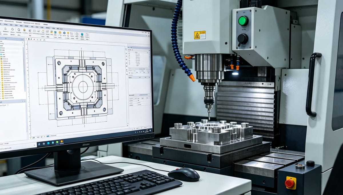
| 2 | Design Workflow | Product Analysis → Material Selection → 3D Parting → Gating → Structure → Detail Drawings → BOM. |
| 3 | Demolding | • Smooth: Standard ejection.• Force: Stripping (for flexible plastics like PP). |
| 4 | Springs | Provide rebound force for mechanisms. |
| 5 | Fits | Clearance, Transition, Interference (Press). |
| 6 | Cooling Lines | Straight-through, Loop, Fountain (Bubbler), Spiral. |
| 7 | Injection Machines | Vertical/Horizontal; by Shot Size (mg to kg); by Clamping Force (Tons). |
| 8 | Mold Sizes | • Small: 15-30 series.• Medium: 30-50 series.• Large: 50+ series. |
| 9 | Cooling Function | Controls mold temperature. |
| 10 | Mold Definition | Tool to shape materials via pressure. |
| 11 | Reverse Engineering | 3D scanning → Surface reconstruction → CAD data generation. |
Fazit
Mastering these 88 points provides a solid foundation for any career in mold design and manufacturing. From understanding the subtle shrinkage differences between ABS and PC to navigating complex CAD standards, attention to detail is what separates a good mold from a great one.
Do you have a specific mold design question? Leave a message below!