Unter Spritzgießen1, Das Design von Spritzgussformen bestimmt direkt die Produktqualität, die Produktionseffizienz und die Herstellungskosten. Im Folgenden finden Sie eine umfassende Aufschlüsselung der wichtigsten Konstruktionsprinzipien, Verfahren und Schlüsselsysteme, die die professionelle Entwicklung von Spritzgussformen leiten.
Kerndesign Basis
1. Maßgenauigkeit & Korrektheit der zugehörigen Maße
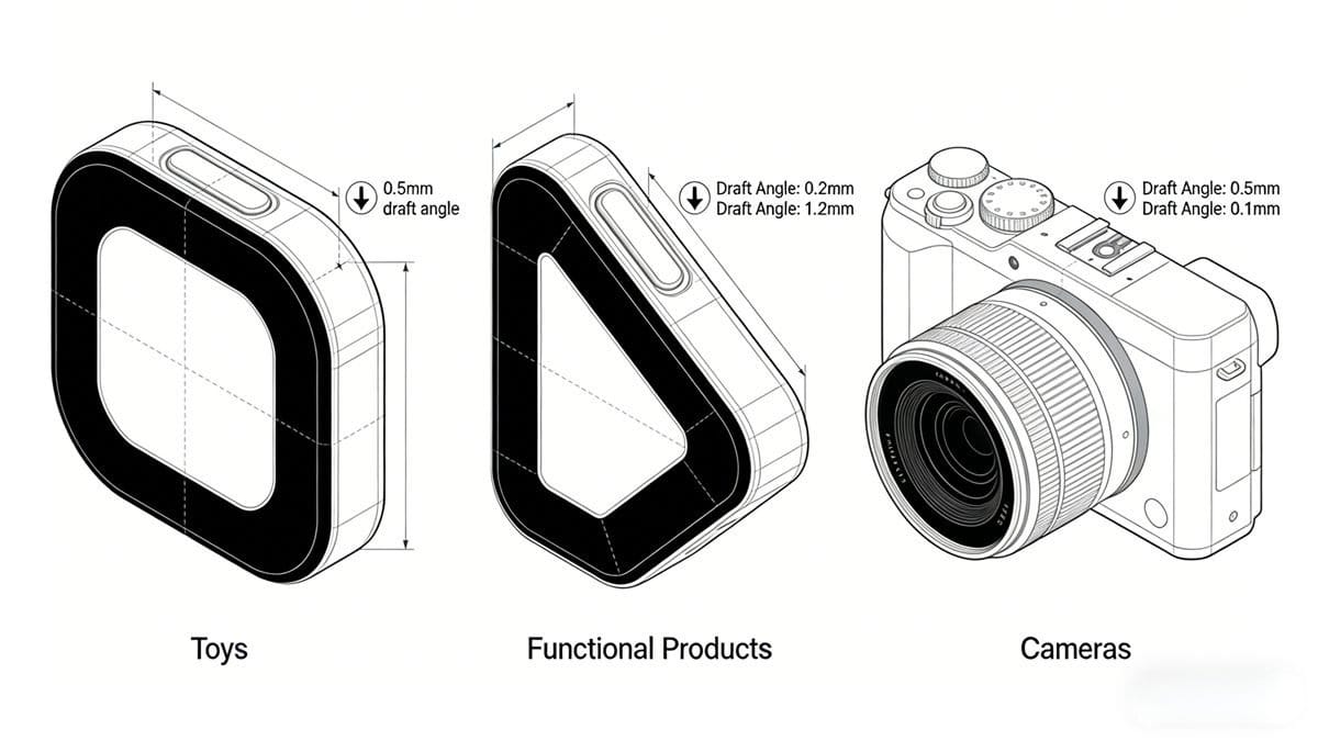
Die äußere Qualität und die spezifischen Abmessungen von Kunststoffprodukten werden durch ihre funktionalen Anforderungen definiert:
- Auf das Aussehen ausgerichtete Produkte (z. B. Spielzeug): Hohe ästhetische Ansprüche, aber mäßige Maßgenauigkeit.
- Funktionelle Produkte: Strenge Maßtoleranzen zur Gewährleistung der Leistung.
- Hochpräzise Produkte (z.B. Kameras): Strenge Anforderungen an Aussehen und Abmessungen.
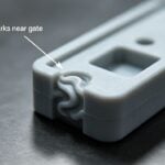
2. Rationalität des Tiefgangwinkels2
Der Entformungswinkel ist entscheidend für eine reibungslose Entformung und Produktintegrität:
- Achten Sie auf ausreichenden Luftzug, um ein Verkleben beim Auswerfen zu verhindern.
- Richten Sie den Winkel an der Oberfläche der Trenn-/Spaltform aus.
- Vermeiden Sie Kompromisse beim Aussehen oder der Genauigkeit der Wandstärke.
- Verhindern Sie die Schwächung von kritischen Strukturbereichen.
Standard-Design-Verfahren
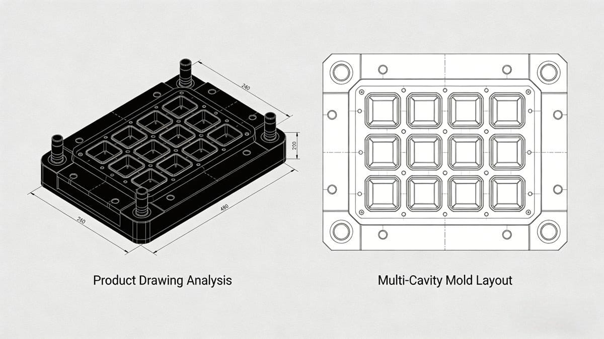
1. Analyse von Produktzeichnungen & physischen Mustern
Bewerten Sie das Produkt gründlich, um die Designeinschränkungen zu ermitteln:
- Geometrische Form und strukturelle Komplexität.
- Maßangaben, Toleranzen und Konstruktionsnullpunkte.
- Technische Anforderungen (z.B. Kraft, Flexibilität).
- Anforderungen an das Kunststoffmaterial und die Oberflächenbeschaffenheit.
2. Anzahl der Hohlräume & Layout
Bestimmen Sie die Anzahl der Kavitäten anhand von:
- Produktgewicht vs. Kapazität der Spritzgussmaschine.
- Projizierte Fläche vs. Klemmkraft.
- Größe der Form im Vergleich zum Holmabstand der Maschine.
- Produktpräzision, Farbe und Produktionsvolumen.
- Wirtschaftliche Effizienz (Produktionswert pro Form).
Überlegungen zum Hohlraumlayout:
- Optimieren Sie die Größe der Form und die Balance des Anschnittsystems.
- Koordinieren Sie sich mit Kernziehmechanismen, Einsätzen und Kühlsystemen.
- Passen Sie den Wert anhand der Trennfläche und der gewählten Anschnittposition an.
Wichtige Design-Elemente
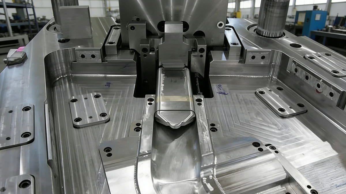
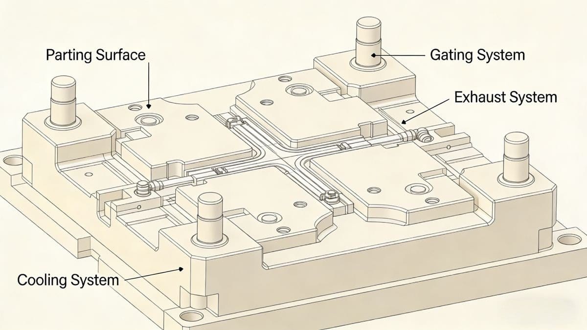
1. Auswahl der Trennfläche
Die Trennfläche sollte:
- Bewahren Sie das Aussehen und die Präzision des Produkts.
- Vereinfachen Sie die Bearbeitung von Formen (insbesondere die Herstellung von Kavitäten).
- Erleichtern Sie die Integration von Anschlüssen, Abgas- und Kühlsystemen.
- Stellen Sie sicher, dass das Produkt auf dem bewegliche Form beim Entformen.
- Kann problemlos mit Metalleinsätzen bestückt werden.
2. Entwurf des Gating-Systems
Das Gating-System kontrolliert den Kunststofffluss in die Kavität. Die wichtigsten Schritte:
- Auswahl der Gate-Position (Befolgen Sie diese Grundsätze):
- Zur einfachen Reinigung auf der Trennfläche anbringen.
- Achten Sie auf den gleichen Abstand zu allen Hohlräumen (kürzester Fließweg).
- Leiten Sie den Fluss in Richtung der dickwandigen Abschnitte für eine gleichmäßige Befüllung.
- Vermeiden Sie das Auftreffen auf Kerne/Einsätze (verhindert Verformung).
- Minimieren Sie Schweißnähte oder platzieren Sie sie in unkritischen Bereichen.
- Ermöglicht eine gleichmäßige Befüllung und eine effiziente Gasabfuhr.
- Positionieren Sie es für eine einfache Nachbearbeitung, ohne das Erscheinungsbild zu beeinträchtigen.
- System Komponenten:
- Anguss: Hauptkanal, der die Spritzgussmaschine mit der Form verbindet.
- Läufer: Verteilt den Kunststoff auf mehrere Hohlräume (optimiert den Querschnitt für den Fluss).
- Tor: Steuert Durchflussmenge und Druck (z.B. Pin-Point, Edge oder Sub-Gates).
- Degating-Mechanismus: Für punktgenaue Anschnitte, um die Trennung der Läufer beim Auswerfen zu gewährleisten.
3. Auspuffanlage Design
Eine wirksame Entlüftung verhindert Defekte wie Lufteinschlüsse und Brandflecken:
- Lüftungsschlitze: Positionieren Sie an den zuletzt gefüllten Hohlräumen. Die Tiefe variiert je nach Material:
- ABS: ≤0,04 mm
- Spachtelmasse: ≤0,02 mm
- POM (Delrin): ≤0,02 mm
- Entlüftung: Verwenden Sie Zwischenräume zwischen den Kernen, Auswerferstifte oder spezielle Auspuffstopfen.
- Air Pins: Verhindern Sie die Verformung des Vakuums beim Auswerfen des Produkts.
- Anti-Vakuum-Komponenten: Vermeiden Sie das Anhaften des Produkts auf der Oberfläche der Form.
4. Design des Kühlsystems3
Die gleichmäßige Kühlung gewährleistet eine gleichbleibende Produktqualität und eine Reduzierung der Zykluszeit. Design-Überlegungen:
- Anordnung der Kühlkanäle (z.B. parallel, seriell oder spiralförmig).
- Position und Größe der Kanäle (vermeiden Sie die Beeinträchtigung anderer Formkomponenten).
- Gezielte Kühlung für Bereiche mit hoher Hitzeentwicklung (z.B. Kerne, Einsätze, Schieber).
- Auswahl an Standard-Kühlkomponenten (Rohre, Ablenkbleche, O-Ringe).
- Versiegeln der Struktur, um das Austreten von Wasser zu verhindern.
Notiz
Das Design von Spritzgussformen ist ein iterativer Prozess - jedes System steht in Wechselwirkung mit anderen. Das Gleichgewicht zwischen Funktionalität, Herstellbarkeit und Kosten erfordert eine sorgfältige Anpassung an die spezifischen Produktanforderungen.
Mit dieser Ressource können Sie sich ein umfassendes Wissen über das Spritzgießen aneignen und so Ihre Design- und Produktionseffizienz steigern. ↩
So können Sie besser verstehen, wie die Entformungsschrägen die Produktintegrität und die Effizienz der Entformung beeinflussen. ↩
Eine effektive Kühlung ist entscheidend für die Erhaltung der Produktqualität und die Verkürzung der Zykluszeiten. ↩