Are your plastic parts failing under stress? Standard materials often can't handle tough jobs, leading to costly failures. Long Fiber Thermoplastics (LFT) provide an incredible solution.
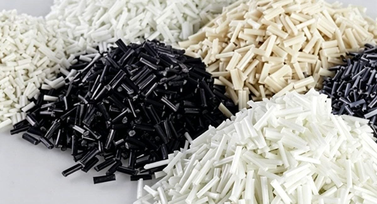
Long Fiber Thermoplastic (LFT) is a composite material that combines long strands of reinforcing fibers, like glass or carbon, with a polymer resin. This creates an internal fiber "skeleton" inside the molded part, giving it exceptional strength, stiffness, and impact resistance far beyond conventional plastics.
I've seen many clients struggle with parts that just weren't strong enough. They needed something that could replace metal but was lighter and easier to shape. That's where our journey with LFT usually begins. It’s a material that truly changes what's possible with plastic. But to get the most out of it, you need to understand how it works, how to design for it, and when to use it. Let's dive into the details and explore how you can use LFT to make your products better.
What Is The Core Advantage Of LFT Plastic?
Do you need stronger parts without the weight and cost of metal? Traditional plastics often crack or deform under high loads. LFT's internal fiber network offers a powerful alternative.
The main advantage of LFT is its internal fiber skeleton. This interconnected network distributes stress across the entire part, just like rebar in concrete. This results in amazing improvements in strength, stiffness, and impact resistance compared to short-fiber plastics.

The real magic of LFT happens inside the part. When we inject the molten plastic into the mold, those long fibers intertwine. They form a robust, three-dimensional skeleton. This structure is what sets LFT apart. It's not just about adding filler; it's about creating an internal frame. I remember a project for an automotive client where we replaced a steel bracket with an LFT-PP part. The LFT version was 40% lighter but passed all the same vibration and load tests. This was only possible because the long fiber network could handle the stress.
How the Fiber Skeleton Works
The length of the fibers is critical. In short-fiber thermoplastics (SFT), the fibers are too short to effectively transfer load from one to another. They act more like isolated islands. In LFT, the fibers are long enough to overlap and interlock, creating a continuous path for stress to travel.
Performance Comparison
Let's look at how this internal skeleton translates to real numbers. This table shows a typical comparison between a base polymer, the same polymer with short fibers, and with long fibers.
| Property | Unreinforced PP | Short Fiber PP (30%) | Long Fiber PP (30%) |
|---|---|---|---|
| Tensile Strength | 낮음 | Medium | 높음 |
| Impact Strength | 낮음 | Medium | Very High |
| Creep Resistance | Poor | Good | Excellent |
| Stiffness (Flex Modulus) | 낮음 | 높음 | Very High |
This shows why LFT is a game-changer for structural applications.
How Should You Design Molds For LFT Materials?
Are you worried that your expensive LFT parts won't perform as promised? Poor mold design can break the long fibers, completely destroying the material's strength and wasting your investment.
To design molds for LFT, you must prioritize protecting fiber length. This means using large, gentle runners and gates, avoiding sharp corners, and maintaining uniform wall thickness. This ensures the fiber skeleton forms correctly, delivering the performance you expect.

I can't stress this enough: the mold is everything when it comes to LFT. You can have the best material in the world, but a bad mold will turn it into expensive, underperforming plastic. The goal is to treat the fibers gently as they flow into the mold cavity. Think of it like moving a long, delicate object through a series of doors. You need wide, smooth passageways, not tight, sharp turns. We once had to troubleshoot a part that was failing impact tests. The issue wasn't the material; it was a small, pinpoint gate that was shearing the fibers as they entered the mold. A simple design change to a larger fan gate solved the problem completely.
Key Mold Design Principles
To get it right, we focus on a few critical areas. Each one is designed to minimize damage to the fibers.
Gate Design
The gate is the entry point into the part cavity, and it's the most common place for fiber damage.
- Do: Use large, full-round or fan-style gates. This allows the material to enter with minimal shearing.
- Don't: Use small, restrictive gates like pin gates or submarine gates. They will break the fibers.
Runner System
The runners are the channels that carry the plastic from the machine nozzle to the gates.
- Do: Keep runners as short and direct as possible. Use generous, rounded corners instead of sharp 90-degree turns.
- Don't: Use long, complex runner systems with sharp bends.
벽 두께
Consistent wall thickness helps the material flow evenly.
- Do: Design parts with uniform wall thickness. If thickness changes are needed, make them gradual.
- Don't: Have abrupt changes from thick to thin sections, as this can disrupt fiber flow and create weak spots.
| Mold Feature | Good Practice (Protects Fibers) | Bad Practice (Damages Fibers) |
|---|---|---|
| Gates | Large fan gates, tab gates | Small pin gates, sub gates |
| Runners | Full round, short, with gentle curves | Long, rectangular, with sharp turns |
| Corners | Generous radii on all corners | Sharp internal and external corners |
How Do Process And Physics Affect LFT Parts?
Are your LFT parts showing weak spots or failing unexpectedly? The way you inject the material directly controls fiber alignment, and this alignment determines the part's final strength.
The injection molding process controls the orientation of the long fibers. This creates different strength properties in different directions, a phenomenon called anisotropy. Controlling melt temperature, injection speed, and pressure is key to managing this and creating strong, reliable parts.

Understanding fiber orientation is where art meets science in LFT molding. As the molten plastic flows into the mold, the fibers tend to align themselves in the direction of that flow. This is especially true near the surface of the part. In the core, where the flow is slower, the fibers are more randomly oriented. This creates a part that is very strong in the direction of flow but weaker perpendicular to it. We had a case with a long, thin part that needed to be stiff along its length. By carefully positioning the gate at one end, we ensured the fibers aligned lengthwise, giving us the exact performance needed. If we had gated it from the side, the part would have been weak and failed.
Understanding Anisotropy
Anisotropy simply means that a material has different properties in different directions.
- High Strength: In the direction of polymer flow, where fibers are aligned.
- Lower Strength: Perpendicular to the direction of flow.
This is a critical design consideration. You must anticipate the direction of stress in your final application and design the mold (especially the gate location) to align the fibers in that same direction.
The Problem with Weld Lines
A weld line forms where two separate flow fronts of plastic meet and fuse. In LFT parts, these are very weak areas because the fibers do not cross the weld line. They flow up to it and then stop, creating a fiber-depleted zone.
| Processing Parameter | Effect on Fiber Length | Effect on Fiber Orientation |
|---|---|---|
| 사출 속도 | High speed can cause breakage | Affects alignment (skin vs. core) |
| 배압 | High pressure increases shearing | Can improve fiber dispersion |
| 용융 온도 | Too high can degrade polymer | Affects flow and thus orientation |
| Gate Location | No effect on length | The most critical factor for orientation |
Mastering these process controls is how we ensure that the final part has the strength where it's needed most.
When Should You Avoid Using LFT?
Is LFT the perfect solution for every single project? Absolutely not. Using this advanced material in the wrong application can be a very expensive and unnecessary mistake.
You should avoid LFT for parts with extremely complex, thin-walled geometries where fibers cannot flow properly. It is also not cost-effective for low-stress applications or when perfectly uniform (isotropic) properties are required in all directions.

I always tell my clients that choosing the right material is just as important as the design itself. LFT is a high-performance, premium material. Using it for a simple cosmetic cover is like using a race car for a trip to the grocery store—it's overkill and not what it was designed for. You pay a premium for those long fibers, and if your application doesn't need that level of impact strength or stiffness, you are simply wasting money. The key is to match the material's capabilities to the product's real-world demands. We always start a project by asking, "What problem are we trying to solve?" If the answer isn't related to high strength, impact resistance, or replacing metal, then LFT is probably not the right choice.
Cost Considerations
LFT materials are significantly more expensive than unreinforced or even short-fiber reinforced plastics. The high performance comes at a high price. If a cheaper material meets all the product requirements, use it.
Geometric Complexity
The benefits of LFT depend on the long fibers being able to flow and form their internal skeleton.
- Very Thin Walls: In sections thinner than 2-3mm, it's difficult for the long fibers to move without breaking or getting stuck.
- Complex Features: Numerous sharp corners, ribs, and bosses can disrupt flow, creating fiber-depleted zones and weld lines that become weak points.
Isotropic Needs
Some applications, like pressure vessels, need uniform strength in all directions (isotropy). LFT is inherently anisotropic (stronger in one direction). In such cases, a different material or manufacturing process might be more suitable. For example, an unreinforced, high-strength polymer might perform more predictably if uniform strength is the top priority.
How Does LFT Compare To Short Fiber Reinforced Plastics?
Are you confused about the difference between long fiber and short fiber plastics? They may sound similar, but their performance in demanding applications is worlds apart. Choosing the wrong one can lead to failure.
LFT uses fibers over 10mm long that create a structural skeleton, delivering massive gains in impact strength and toughness. Short Fiber Thermoplastic (SFT) uses fibers under 1mm that act as simple fillers, providing a modest increase in stiffness and strength.

The difference between LFT and SFT is the most common point of confusion I see with new clients. It's easy to think, "fiber is fiber," but that's not true. The length is what makes all the difference. Think of it this way: SFT is like mixing sand into concrete. It makes it a bit harder. LFT is like putting steel rebar into the concrete. It turns it into a true structural material capable of bearing heavy loads and absorbing huge impacts. When a customer brings us a part that needs to survive drops, impacts, or constant vibration, we immediately start the conversation about LFT. For simple enclosures or parts that just need to be a little stiffer than standard plastic, SFT is often a great, cost-effective choice.
Head-to-Head Comparison
This table breaks down the key differences between LFT and SFT, helping you see where each one shines.
| Feature | Short Fiber Thermoplastic (SFT) | Long Fiber Thermoplastic (LFT) |
|---|---|---|
| Fiber Length | < 1 mm | > 10 mm (in pellet), 3-5mm+ (in part) |
| Primary Benefit | Increased stiffness and strength | Massive increase in impact strength & toughness |
| Mechanism | Simple filler reinforcement | Forms an internal structural skeleton |
| Impact Strength | Moderate improvement | Excellent, often 5-10x higher than SFT |
| Creep Resistance | Good | Excellent |
| 표면 마감 | Generally smoother | Can show fiber pattern on surface |
| Cost | Lower | Higher |
| Typical Use Case | Housings, brackets, levers | Structural components, metal replacement |
Choosing between them comes down to one question: is your part a simple component, or is it part of the structure? If it needs to withstand major forces, LFT is the clear winner.
결론
LFT offers unmatched strength by creating an internal fiber skeleton. For demanding applications, it's the key to replacing metal and achieving superior performance in your plastic parts.
At IDEAL PRO, we don’t just mold plastic; we engineer success. Our mission, “Sustainable Solutions, Enduring Excellence,” drives us to look beyond the immediate transaction. We are dedicated to forging partnerships that deliver tangible cost savings, enhanced quality, 및 production efficiency for the long haul. We don't stop at solving the problem; we provide the ongoing insights that keep your product ahead of the curve.
Don’t let outdated designs weigh you down. Whether you are looking to replace steel components or optimize an existing assembly, IDEAL PRO is ready to turn your vision into a high-performance reality.
Contact IDEALPRO today. Let’s build a lighter, stronger, and more sustainable future together.