Injection Molding Bubbles: Causes, Identification, and Solutions
Bubbles in injection molded parts are a common yet critical defect. Unless intentionally designed for aesthetic purposes, trapped air is strictly unacceptable in transparent products. More importantly, bubbles compromise the mechanical strength of the part and can lead to failing specific weight requirements.
To effectively troubleshoot this issue, we must first understand that injection molding bubbles generally fall into three distinct categories: Air Entrapment, Moisture (Water Vapor), 및 Vacuum Voids.
1. Air Entrapment: Trapped Gases
Air can enter the molding process from two main sources: the plastic pellets in the barrel and the mold cavity itself.
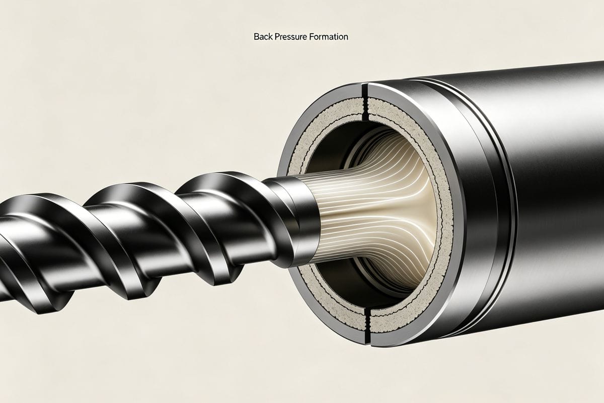
Barrel Air and Back Pressure
As plastic pellets travel from the hopper into the barrel, air is naturally carried with them. During plasticization, applying adequate 역압 compresses the melt in front of the screw, popping the air bubbles before they are injected into the mold.
- Machines without back pressure gauges: Operators must estimate back pressure by observing the screw retraction speed, as the flow control valve angle does not have a linear relationship with pressure.
- Machines with back pressure gauges: Note that the gauge typically reads hydraulic pressure, not the actual melt pressure. There is usually a ~10:1 ratio between hydraulic and melt pressure. Always refer to your machine’s conversion chart.
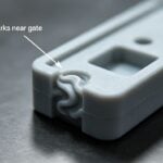
Mold Cavity Air & Injection Speed
If the air inside the mold cavity cannot escape, it mixes with the incoming melt. High injection speeds (e.g., using nitrogen acceleration) can trap air, especially in thin-wall molding.
Solutions for Air Entrapment:
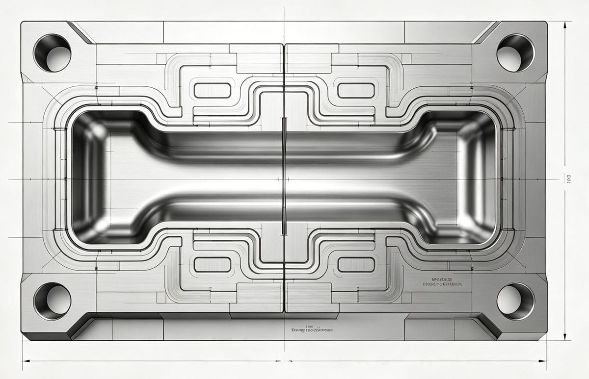
- Optimize Venting: Vents on the parting line should be no deeper than 0.03 mm and at least 6 mm wide, spaced every 25–50 mm.
- Optimize Clamping Force: Use the minimum clamping force necessary to prevent flash. Excessive force crushes the vents, trapping air and reducing the lifespan of the mold and machine toggle mechanism.
- Venting Steel: For matte-finish parts, porous venting steel can be used to allow air to escape through micro-pores.
- Vacuum Venting: For hard-to-reach areas, a vacuum pump can extract air during injection. (Note: Vacuum venting and venting steel cannot be used simultaneously).
2. Moisture (Water Vapor)
Plastic pellets absorb moisture from the atmosphere. If not thoroughly dried before reaching high temperatures (>100°C), this water turns to steam and forms bubbles inside the part.
Sizing Your Drying Hopper Correctly
A common mistake is using a drying hopper that is too small. To ensure proper drying, calculate the required hopper capacity using this formula:
H = (3.6 × s × t) / c
- H = Hopper capacity (kg)
- s = Shot weight including runner (g)
- t = Required drying time (hours)
- c = Cycle time (seconds)
| Parameter | 설명 | Unit |
|---|---|---|
| H | Required Hopper Capacity | kg |
| s | Shot Weight (with runner) | g |
| t | Material Drying Time | Hours |
| c | Machine Cycle Time | Seconds |
Example Calculation: For a 32-cavity PET preform mold (20g per shot) with a 24-second cycle and a required 5-hour drying time: H = (3.6 × 32 × 20 × 5) / 24 = 480 kg. (Relying solely on generic supplier charts often results in undersized hoppers, leading to moisture-related bubbles).
Advanced Drying Solutions
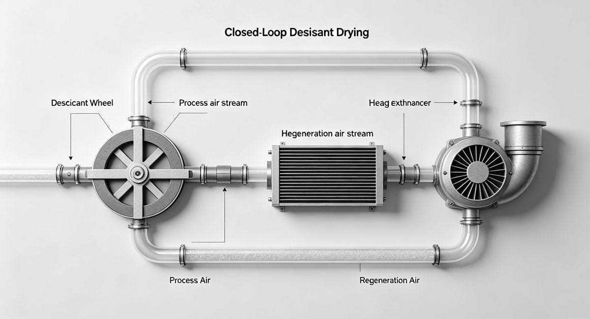
- Desiccant Dryers: Standard hopper dryers struggle in high-humidity environments (e.g., >90% RH). Desiccant dryers use a closed-loop system with molecular sieves to achieve a dew point of -40°C, completely independent of ambient humidity.
- Two-Stage Drying: For cost-effective upgrades, a two-stage drying hopper can provide better moisture removal than a single standard hopper.
- Temperature Control: Always follow the resin supplier's recommended drying temperature. Excessive heat can degrade the polymer, affecting color, transparency, and mechanical properties.
3. Vacuum Voids (Shrinkage Bubbles)
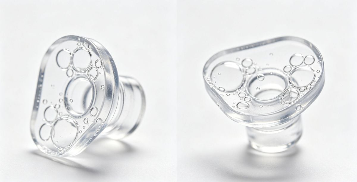
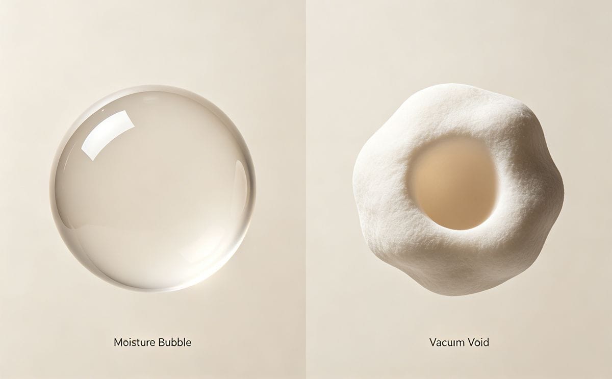
Vacuum voids are common in thick-walled parts. They occur when the outer skin of the plastic cools and solidifies while the inner core remains molten. As the core cools and shrinks, it pulls inward, creating a void. These bubbles contain no air or moisture—only a vacuum.
솔루션:
- Treat vacuum voids exactly like sink marks.
- Ensure the cold runner diameter is proportional to the maximum wall thickness, allowing holding pressure to pack more material into the cavity before the gate freezes.
How to Identify the Type of Bubble
Since the solutions differ drastically, accurate identification is crucial. For transparent or translucent parts, use the following diagnostic matrix:
| Diagnostic Factor | Air / Moisture Bubbles | Vacuum Voids |
|---|---|---|
| Quantity | Multiple, random occurrences | Usually one, or very few |
| Location | Random positions across different parts | Always in the thickest section of the part |
| Heat Test | Expands when heated | Shrinks or causes surface depression when heated |
| Shape | Perfectly spherical | Irregular or elongated shape |
결론
Eliminating bubbles in 사출 성형 requires a systematic approach. By correctly identifying whether the defect is caused by trapped air, moisture, or vacuum shrinkage, you can apply the precise mechanical or process adjustments needed to restore part quality and structural integrity.
Have you encountered stubborn bubble defects in your molding process? Share your experiences or questions in the form below!