Designing for LSR molding seems simple, but hidden traps can ruin your project. These mistakes lead to failures and wasted costs. Let's cover the key points to succeed.
Key considerations for LSR injection molding include managing its unique low viscosity and thermal expansion. This means focusing on precise shrinkage rates, strategic parting lines, adequate venting, proper injection points, easy demolding, durable mold materials, and consistent temperature control for successful, high-quality parts.

When I first started with Liquid Silicone Rubber (LSR), I thought its process was just like thermoplastic molding. I quickly learned that while the principles are similar, the details are worlds apart. LSR's unique properties, like its low viscosity and thermal behavior, demand a completely different mindset for mold design. It's a lesson you learn fast, often after a few failed attempts. Understanding these differences is the first step toward mastering LSR molding and avoiding costly revisions down the road. Let's break down the essential factors you need to get right from the very beginning.
How Does the Shrinkage Rate Affect Your LSR Mold Design?
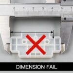
Ignoring LSR's unique shrinkage can completely warp your parts. This subtle factor ruins precision and part fit. We must calculate it correctly from the start to ensure accuracy.
LSR has a high, non-linear shrinkage rate, typically between 2% and 4%. This rate is influenced by material grade, curing temperature, and injection pressure. Precise calculation is critical for dimensional accuracy and preventing part defects like warping or incorrect fits in assemblies.

Unlike thermoplastics that simply shrink as they cool, LSR has a more complex behavior. It actually expands inside the hot mold during the curing process and then shrinks significantly as it cools to room temperature. This is a critical point that many designers miss. I remember a project for a medical device seal where we used a standard shrinkage value. The first parts came out undersized because we hadn't accounted for the specific grade's thermal expansion in the mold. We had to adjust the tooling, which cost us time and money. To avoid this, you must consider several factors that influence the final shrinkage.
Factors Influencing LSR Shrinkage
| Factor | Impact on Shrinkage | Design Consideration |
|---|---|---|
| Material Grade | Different grades have different filler content and properties. | Always consult the material supplier's datasheet for specific shrinkage data. |
| 金型温度 | Higher temperatures can lead to more expansion, affecting the final shrinkage. | Maintain a consistent and uniform mold temperature for predictable results. |
| Part Thickness | Thicker sections will shrink more than thinner sections. | Design parts with uniform wall thickness to minimize internal stresses and warping. |
| 射出圧力 | Higher packing pressure can reduce overall shrinkage slightly. | Optimize pressure settings during the molding trial to fine-tune dimensions. |
Why Is the Parting Line So Critical for LSR Molds?
A poorly designed parting line with LSR is a recipe for flash. The material's low viscosity allows it to escape through the tiniest gaps, creating messy, unusable parts.
The parting line in an LSR mold must be extremely precise and perfectly matched. Because LSR has a water-like viscosity before curing, any microscopic gap can cause flash. A clean, well-designed parting line is essential for producing high-quality, flash-free parts.

I can't stress this enough: precision is everything when it comes to the parting line for an LSR mold. On one project, we were creating a flexible keypad. The mold's parting line had a very minor mismatch, something that would have been acceptable for a thermoplastic like ABS. But with LSR, it was a disaster. The material bled out, creating a thin, frustrating film of flash around every single part that required extensive manual trimming. We had to take the mold offline and re-machine the surfaces to achieve a perfect seal. This experience taught me that you must design the parting line not just for part separation, but as a perfect sealing surface. It should be located on the flattest, most stable area of the part possible to ensure the clamping force is distributed evenly and creates a tight seal.
Parting Line Best Practices
- Zero Tolerance: Aim for a "zero-tolerance" fit between the mold halves. This requires high-precision machining and grinding.
- Simple Geometry: Whenever possible, design the parting line to be a simple, flat plane. Complex, stepped parting lines are much harder to seal.
- Avoid Sharp Corners: Place parting lines on rounded edges if possible to reduce wear and improve sealing over the life of the mold.
How Do You Ensure Proper Venting in an LSR Mold?
Trapped air is a common enemy in LSR molding. The material fills the mold so quickly that air has no time to escape, leading to bubbles and incomplete parts.
Effective venting is crucial for LSR molds to prevent air entrapment. Because of LSR's low viscosity and rapid fill times, vents must be placed strategically at the end of the flow path and in any areas where air could be trapped.

Think of pouring water into a bottle—if you pour too fast, air gets trapped and bubbles back up. LSR behaves in a similar way inside a mold. It flows so easily and cures so quickly that any trapped air gets locked into the final part, creating voids that compromise its structural integrity or appearance. We once had an issue with a transparent LSR lens where tiny air bubbles were consistently showing up in the same spot. We realized it was a dead end in the flow path with no way for the air to escape. The solution was to add a very shallow vent channel, just 0.005mm deep, in that exact spot. The LSR is too thick to flow into such a small gap, but the air escapes easily. This small change completely solved the problem. For complex parts, we often recommend using a vacuum system that pulls all the air out of the cavity just before injection, guaranteeing a perfect, bubble-free fill every time.
Where Should You Place the Injection Point in an LSR Design?
The location of your injection gate is not a minor detail. It determines how the material flows, where weld lines form, and even how well the part functions.
The injection point, or gate, should be placed in the thickest section of the part to ensure uniform filling and minimize defects. Using a cold runner system is highly recommended for LSR to prevent the material from curing before it enters the mold cavity.

Choosing the right gate location is a strategic decision. You want the LSR to flow from a thick section to a thin section, which helps push air out towards the vents and ensures the entire cavity is filled before the material starts to cure. A poorly placed gate can create "weld lines" where two flow fronts meet. While sometimes unavoidable, these lines can be weak points in the part. I worked on a project for a flexible O-ring where the gate was placed directly opposite a critical stress point. During testing, the O-rings kept failing right on the weld line. We had to re-tool the mold to move the gate to a less critical area, which solved the strength issue. This is why we almost always use a cold runner system for LSR. It keeps the material cool right up to the gate, so it only starts curing once it's inside the hot mold cavity. This gives us much better control over the process and eliminates material waste in the runner.
What's the Best Strategy for Demolding LSR Parts?
Getting the finished part out of the mold can be surprisingly difficult. LSR is flexible and sticky, and it doesn't behave like rigid thermoplastics during ejection.
Demolding LSR requires careful planning because the parts tend to stick to the mold cavity with the largest surface area, not necessarily the core. Strategic use of ejector pins, air assistance, and robotic grippers is often necessary for clean removal.

Here’s another counter-intuitive thing about LSR: it doesn't always stick to the moving half of the mold (the core). Because it expands with heat, it tends to grip onto whichever surface it has the most contact with. This often means it stays in the stationary half (the cavity). I recall a project for a complex bellow part. We assumed it would stick to the core, so we placed all the ejector pins there. In the first trial, the part stubbornly stayed in the cavity, and the ejector pins just pushed against empty space. We had to add ejectors to the other side and use a blast of air to help release the part. For delicate or complex parts, automated removal with robotic arms is the best way to ensure parts aren't damaged or deformed during demolding. You have to think about how the part will be removed right from the initial design stage.
Which Mold Material Should You Choose for LSR Molding?
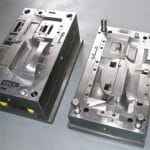
Your choice of mold material directly impacts the tool's lifespan and the quality of your parts. LSR molding is a demanding process, and not just any steel will do.
Molds for LSR should be made from high-quality, pre-hardened, or through-hardened steel like P20 or H-13. The material must withstand high molding temperatures and the potentially abrasive nature of some LSR grades to ensure longevity and consistent part quality.

LSR molds operate at high temperatures, typically between 170°C and 200°C (340°F to 390°F). Softer materials like aluminum are not suitable because they can't handle the thermal cycling and will wear out quickly. You need robust tool steel. For prototyping or low-volume runs, a pre-hardened steel like P20 can be a cost-effective choice. However, for high-volume production, especially with abrasive LSR grades that contain fillers like glass, you must use a tougher, through-hardened steel such as H-13. I've seen molds made from inferior steel start to show wear and flash after just a few thousand cycles. Investing in the right material from the start saves a huge amount of money in the long run by preventing downtime, repairs, and quality issues. The mold surface finish is also key; a polished surface helps with part release and gives a better cosmetic appearance.
How Does Temperature Control Impact LSR Part Quality?
Consistent temperature is the key to consistent LSR parts. Any variation across the mold surface can lead to curing problems, dimensional instability, and failed parts.
Precise and uniform temperature control is essential for LSR molding. The mold is heated, typically with electric cartridges, to a specific temperature to activate the curing process. Inconsistent heating can lead to under-cured or warped parts and dimensional variations.

This is the complete opposite of thermoplastic molding, where you are actively cooling the mold. With LSR, you are heating it to trigger the platinum-catalyzed curing reaction. The key word here is uniformity. If one part of the mold is hotter than another, the LSR in that area will cure faster. This can create internal stresses in the part, leading to warping as it cools. We use multiple heating cartridges and temperature sensors distributed throughout the mold to ensure the entire cavity surface is at a stable, even temperature. On a project for an automotive gasket, we were seeing inconsistent compression set values. After investigating, we found one of the heating cartridges was failing, creating a cold spot on the mold. Once we replaced it and stabilized the temperature, the part properties became consistent again. This is why a well-designed heating system is a non-negotiable part of any high-quality LSR mold.
結論
Mastering LSR molding requires attention to its unique properties. Getting details like shrinkage, parting lines, venting, and temperature control right ensures high-quality, consistent results for your project.