Injection speed (screw forward speed) is arguably the most critical parameter in the moulage par injection1 process. It has a direct and relationship with the quality of the finished part.
By properly determining the start, middle, and end points of filling speed segments—and achieving a smooth transition between set points—you can maintain a constant melt surface speed. This ensures optimal molecular orientation and minimizes internal stress.
Key Takeaway: The goal of velocity profiling is to keep the melt front velocity (MFV) constant throughout the filling phase.
1. Core Principles of Speed Segmentation
To achieve high-quality molding, we recommend adhering to the following fundamental principles:
- Constant Surface Speed: The velocity of the fluid front should remain constant.
- Prevent Freezing: Use rapid injection to prevent the melt from freezing prematurely during the process.
- Critical Area Management: Balance high speed in runners with reduced speed at the gate (entry point).
- Precision Stopping: The speed must ensure the cavity stops filling immediately after being full to prevent over-packing, flash, and residual stress.
- Geometry Awareness: Settings must account for mold geometry, flow restrictions, and instability factors.
2. The Relationship Between Material and Speed
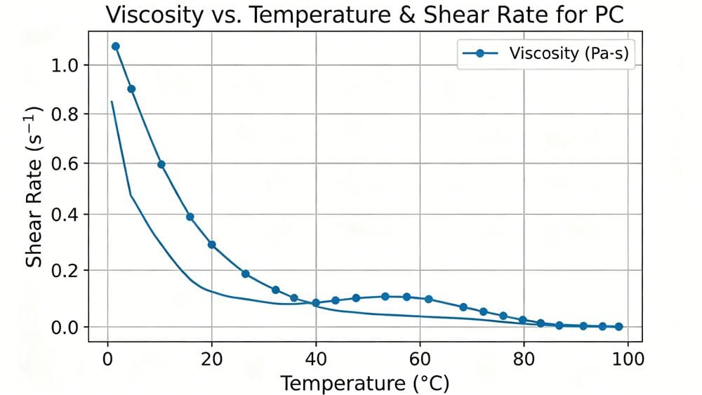
Material characteristics are paramount. Polymers can degrade due to excessive stress. While increasing melt temperature can lead to oxidation, shear-induced degradation is often the bigger risk.
However, higher temperatures reduce viscosity, which lowers shear stress. Multi-stage injection speeds2 are particularly helpful for heat-sensitive materials like PC (Polycarbonate), POM (acétal), et UPVC.
Shear Sensitivity vs. Viscosity
| Type de matériau | Viscosity Characteristic | Stratégie de vitesse | Risk Factor |
|---|---|---|---|
| PC, POM, UPVC | Heat Sensitive | Multi-stage / Controlled | Thermal degradation & Shear stress |
| Glass-Filled Nylon | High Sensitivity | Smooth Transitions | Fiber breakage & Surface finish |
| High Viscosity (e.g., PC) | High Resistance | Slower at Gate | Cold slugs entering cavity |
3. Mold Geometry: The Deciding Factor
The physical shape of your mold dictates your speed profile:
- Thin Walls: Require maximum injection speed to fill before freezing.
- Thick Walls: Require a Slow-Fast-Slow velocity curve to avoid defects.
- Cross-Sections: Decelerate when the melt front reaches cross-sectional changes.
- Radial Diffusion: Ensure the melt volume increases evenly for complex molds.
- Long Runners: Must be filled rapidly to reduce melt front cooling. Exception: High viscosity materials (like PC) where too much speed drags cold slugs into the cavity.
4. Troubleshooting Defects via Speed Control
Most injection molding defects can be solved by adjusting the injection speed. Here is how to tackle specific issues:
A. Gate Defects (Burn Marks & Flow Lines) When melt passes through the gate, the surface may cool or stagnate due to sudden narrowing. This creates a pressure peak. High pressure damages the material, causing flow marks or gate burn marks.
- Solution : Decelerate just before the gate to prevent excessive shear, then accelerate back to the original speed. Since precise control at the gate is difficult, decelerating in the final section of the runner is often a better approach.
B. Flash and Air Traps
- Flash: Caused by over-packing.
- Air Traps: Caused by poor venting or turbulent flow at the end of the fill.
- Solution : Reduce the speed in the final segment of injection. This prevents over-filling and allows air to escape through vents.
C. Short Shots These occur when speed is too slow at the gate or flow is obstructed.
- Solution : Increase injection speed immediately after passing the gate or local flow obstructions.
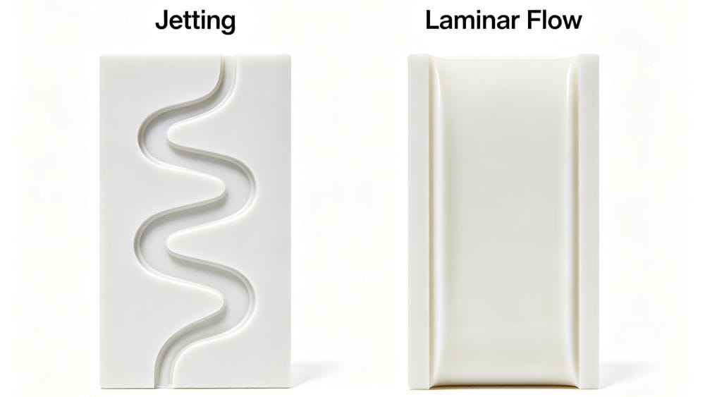
D. Jetting (Snake-like flow) To prevent jetting, the speed setting must ensure rapid filling of the runner area, followed by a slow speed through the gate.
- The Challenge: Finding the conversion point. Too early increases cycle time; too late causes jetting due to inertia. Low viscosity and high barrel temperature exacerbate this trend.
5. Summary: Defects and Speed Adjustments
For quick reference, use the table below to adjust your parameters:
| Type de défaut | Primary Cause | Speed Adjustment Strategy |
|---|---|---|
| Coup court | Flow obstruction / Slow gate speed | Increase Speed at gate/obstruction |
| Flash | Over-packing / Excessive pressure | Decrease Speed in final segment |
| Burn Marks | Cisaillement excessif au niveau de la porte | Decrease Speed before gate |
| Marques d'évier | Low pressure transfer / Slow speed | Increase Speed (High speed reduces heat loss) |
| Jetting | High inertia at gate | Slow Down at gate entry |
| Wavy Surface | Viscosity changes / Unstable flow | Optimize for Constant MFV |
Conclusion
Ultimately, the smoothness of the part depends on injection speed. Glass-fiber-filled materials are especially sensitive; for instance, dark spots (waviness) are caused by flow instability due to viscosity changes.
Since melt flow rate is difficult to measure directly, operators often rely on screw forward speed or cavity pressure (assuming no check valve leakage) to (calculate) the settings. Mastering the art of velocity segmentation is the key to controlling part quality.