

Introduction
In injection molding, few defects are as frustrating or costly as short shots (underfilling) caused by poor venting. When trapped air creates backpressure exceeding the injection pressure, molten plastic simply cannot fill the cavity. But poor venting is rarely the sole culprit; it often interacts with material flow, machine settings, and mold temperature.
This comprehensive guide breaks down 13 critical failure points and provides actionable engineering solutions to optimize your molding process, reduce scrap rates, and improve part quality. Whether you are a process engineer or a production manager, this troubleshooting framework will help you diagnose root causes faster.
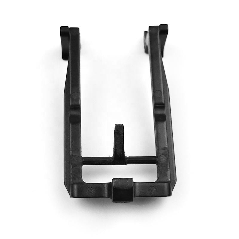
Quick Reference: Top 5 Causes of Poor Venting & Short Shots
For engineers needing immediate answers, here is a structured summary before diving into the detailed analysis.
| Category | Primary Symptom | Immediate Corrective Action | Long-Term Solution |
|---|---|---|---|
| Mold Design | Burn marks at flow end | Clean existing vents; reduce clamp tonnage | Add vent slots (0.02–0.04mm deep) at last fill areas |
| Material | Excessive gas generation | Dry resin thoroughly; check volatiles | Switch to low-viscosity grade; reduce regrind % |
| Process | Incomplete fill at low speed | Increase injection speed & melt temp | Optimize gate location & size for balanced fill |
| Machine | Shot-to-shot variation | Check nozzle temp & heater bands | Repair worn screw/barrel; calibrate thermocouples |
| Part Design | Thin wall hesitation | Raise mold temp; use fast injection | Redesign wall thickness (aim for 1–3mm uniform) |
Detailed Troubleshooting: 13 Root Causes & Engineering Solutions
1. Improper Machine Sizing
The injection machine must be correctly matched to the part weight. The total shot weight (part + runner) should not exceed 85% of the machine’s plasticizing capacity. Undersized machines cannot maintain consistent melt quality, while oversized machines cause residence time degradation.
2. Insufficient Material Feed
Volumetric feeding inconsistencies often stem from non-uniform pellet size or "bridging" in the hopper throat. High temperatures at the feed zone can also cause premature melting and blockage.
- Fix: Ensure proper cooling of the feed throat; verify pellet consistency; check for bridging.
3. Poor Material Flowability
When resin flow is inadequate, mold geometry becomes the limiting factor. Regrind content exceeding recommended limits significantly degrades flow properties.
- Fix: Enlarge gates/runners; add flow enhancers; reduce regrind percentage; optimize sprue bushing diameter.
4. Excessive Lubricant Content
Over-lubrication combined with worn screw check rings causes severe melt backflow, resulting in actual shot volume being less than the setpoint.
- Fix: Reduce lubricant dosage; inspect and replace worn barrel/screw components.
5. Cold Slag & Contamination Blockage
Impurities or cold slugs blocking the nozzle or gate restrict flow entirely.
- Fix: Clean nozzle; enlarge cold slug well; increase runner cross-section.
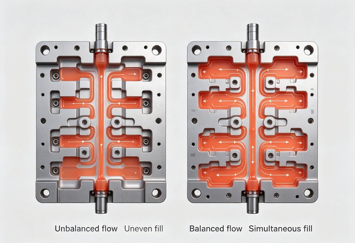
6. Unbalanced Runner System Design
In multi-cavity molds, unbalanced filling causes some cavities to pack out while others starve. Gates positioned in thin-wall sections create immediate flow hesitation.
- Fix: Implement naturally balanced runner layouts; position gates in thick-wall areas; consider multi-point gating for large parts.
7. ⚠️ Mold Venting Deficiencies (Critical Focus)
This is the most common cause of short shots related to air entrapment. When compressed gas pressure exceeds injection pressure, filling stops. Moisture and volatiles exacerbate this by generating additional gas.
Related reading: Analysis of Bubble Formation in Plastic Product Manufacturing
Recommended Vent Specifications
| Mold Feature | Depth (mm) | Width (mm) | Location Notes |
|---|---|---|---|
| Parting Line Vents | 0.02 – 0.04 | 5 – 10 | Along ejector side PL; avoid flash |
| Ejector Pin Vents | 0.02 – 0.05 | Perimeter | At last-fill zones; clean regularly |
| Sintered Metal Inserts | N/A | Custom | Deep pockets where conventional vents fail |
| Vacuum Venting | N/A | N/A | For high-precision optical/medical parts |
- Process Adjustments: Increase mold temperature, reduce injection speed initially, lower clamp force slightly to allow gas escape, and ensure thorough material drying.
8. Mold Temperature Too Low
Cold molds freeze the flow front prematurely. Always preheat molds to specification before production startup.
- Fix: Verify cooling channel design; restrict coolant flow during warm-up; use mold temperature controllers.
9. Melt Temperature Too Low
Melt temperature directly correlates with flow length. Insufficient heat reduces viscosity and fill capability.
- Fix: Allow adequate soak time after reaching setpoint; increase front barrel zone temperature; extend cycle time if low-temp processing is mandatory.
10. Nozzle Temperature Drop
Frequent contact with cooler molds causes nozzle freeze-off. Without a proper cold slug well, frozen material blocks subsequent flow.
- Fix: Maintain nozzle-mold separation during open mold; verify nozzle heater function; install insulated nozzle tips.
11. Insufficient Injection/Holding Pressure
Pressure and fill length are proportional. Low pressure = short shot.
- Fix: Slow injection ramp to build pressure; extend hold time; increase melt temp to reduce viscosity (watch for thermal degradation).
12. Injection Speed Too Slow
Slow flow allows excessive cooling during transit, increasing effective viscosity mid-fill.
- Fix: Increase injection speed profile; use segmented speed control (fast through runners, slow at gate, fast to fill).
13. Poor Part Design (Wall Thickness)
Extreme aspect ratios or walls outside the optimal range cause flow hesitation.
Related guide: Four Aspects That Determine the Accuracy of Thin-Wall Injection Molded Parts
Recommended Minimum Wall Thickness by Material
| Material | Min Thickness (mm) | Optimal Range (mm) | Notes |
|---|---|---|---|
| Polyethylene (PE) | 0.5 | 1.0 – 3.0 | Flexible; tolerates thinner walls |
| Polystyrene (PS) | 0.75 | 1.5 – 3.0 | Brittle; avoid sharp transitions |
| ABS | 0.75 | 1.5 – 3.5 | Good flow; watch for sink marks |
| Nylon (PA) | 0.7 | 1.0 – 3.0 | Crystalline; shrinks significantly |
| PMMA (Acrylic) | 0.7 | 1.5 – 4.0 | High viscosity; needs generous gates |
| PVC | 2.3 | 3.0 – 6.0 | Heat sensitive; avoid thin sections |
| Cellulose Acetate | 0.7 | 1.0 – 3.0 | Hygroscopic; dry thoroughly |
⚠️ Design Rule: Avoid walls >8mm (sink/void risk) or <0.5mm (fill difficulty) unless using specialized micro-molding equipment.
Advanced Prevention Strategies
Beyond reactive troubleshooting, implement these proactive measures:
- Mold Flow Analysis (CAE): Run filling simulations before cutting steel to predict air traps and optimize vent placement.
- Preventive Maintenance Schedule: Regularly clean vents, check heater bands, and measure screw/barrel wear.
- Material Handling Protocol: Implement standardized drying procedures with dew-point monitoring for hygroscopic resins.
- Design for Manufacturing (DFM) Reviews: Engage molding engineers during product design to avoid problematic geometries.
- Scientific Molding Approach: Use decoupled molding techniques to separate fill, pack, and hold phases for robust process windows.
Frequently Asked Questions (FAQ)
Q: How do I distinguish between a venting issue and a flow issue? A: Venting issues typically show burn marks or diesel effect at the last fill area. Pure flow issues show gradual shortening without burning. Try reducing injection speed temporarily—if the short shot worsens, it's likely flow; if it improves, it's likely venting.
Q: Can I fix venting problems without modifying the mold? A: Temporarily, yes. Reduce clamp tonnage, lower injection speed, increase mold temperature, and ensure material is properly dried. However, permanent fixes usually require mold modifications.
Q: What is the ideal vent depth for ABS plastic? A: Typically 0.025–0.038mm (0.001–0.0015 inches). Always start shallow and increase incrementally to avoid flash.
Q: Does regrind percentage affect venting? A: Yes. Higher regrind content increases fines and potential moisture absorption, both of which generate excess gas. Keep regrind below 20% for critical parts.
Conclusion
Poor venting and short shots are multifactorial problems requiring systematic diagnosis. By understanding the interplay between machine capability, material properties, mold design, and process parameters, engineers can move beyond trial-and-error to scientific problem-solving. Start with the quick reference table above, validate with targeted experiments, and implement permanent corrective actions for sustainable production excellence.
Have you encountered a persistent venting challenge? Share your experience in the comments below or contact our engineering team for a consultation.



 English
 French
 Dutch
Dutch German
 Japanese
 Korean