Essential Knowledge About Gas Assisted Injection Molding
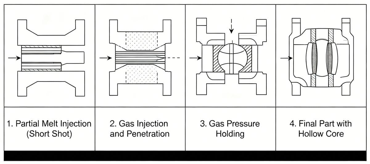
Gas Assisted Injection Molding (GAIM), also known as GRIM, is an advanced 사출 성형 process that has seen widespread application internationally and is increasingly adopted domestically. Its principle involves using a relatively low-pressure inert gas (Nitrogen is commonly used due to its low cost, safety, and cooling properties, with pressures ranging from 0.5 to 300 MPa) to replace a portion of the resin in the mold cavity for holding pressure. This results in molded parts with superior performance.
The Advantages of Gas Assisted Injection Molding
GAIM overcomes the limitations of both traditional injection molding and foam molding, offering several key benefits.
Excellent Part Performance
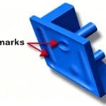
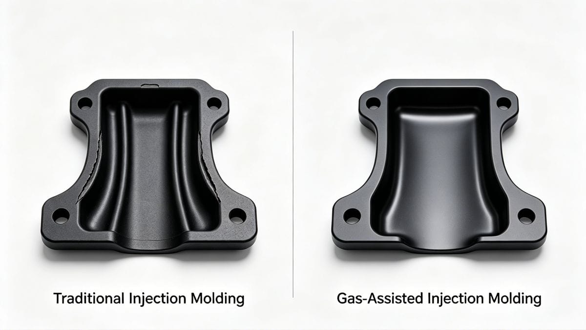
- Eliminates Voids and Sink Marks: By strategically placing gas channels in reinforcing ribs and bosses where wall thickness varies, and introducing gas after a short shot, the process compensates for resin shrinkage during cooling. This effectively prevents the formation of voids and sink marks.
- Reduces Internal Stress and Warpage: During cooling, a continuous gas channel forms from the gas nozzle to the end of the melt flow. This ensures uniform pressure distribution with no pressure loss, significantly reducing residual stress and preventing part warpage.
- Increases Part Strength: The design of hollow reinforcing ribs and bosses results in a strength-to-weight ratio that is approximately 5 times higher than that of similar solid parts. The moment of inertia is also substantially increased, enhancing the part's overall structural integrity.
- Enhances Design Flexibility: GAIM allows for the molding of parts with non-uniform wall thickness. This enables the single-step production of complex parts that would otherwise need to be manufactured in several pieces, simplifying assembly. For instance, a complex car door panel, originally composed of dozens of metal parts, was successfully molded in a single step using GAIM and plastic alloy materials.
비용 효율성
- Saves Raw Materials: By forming cavities in thicker sections of the part, GAIM can reduce the final product weight by 10% to 50%.
- Lowers Equipment Costs: Compared to conventional injection molding, GAIM requires lower injection pressure and clamping force (saving 25% to 50%), and reduces energy consumption by up to 30%.
- Shortens Cycle Time: The removal of core material from thick sections significantly reduces cooling time, potentially by up to 50%.
These advantages make gas assisted injection molding ideal for producing large, flat products like tabletops, doors, and panels; large housings for home appliances, televisions, and office equipment; and structural components such as bases, automotive instrument panels, bumpers, and headlight covers.
Selection of Molding Materials
In theory, all thermoplastics suitable for conventional injection molding can be used in GAIM, including filled resins and reinforced plastics. However, some materials present challenges. Highly fluid plastics like thermoplastic polyurethanes can be difficult to control, while high-viscosity resins require higher gas pressure. Additionally, glass fiber-reinforced materials can cause wear on equipment.
Material selection is critical in GAIM, as the part's wall thickness and surface quality are largely determined by the raw material's properties, and process parameters have limited influence. The table below lists common plastics used in gas assisted injection molding.
| Material Category | Examples | Suitability Notes |
|---|---|---|
| Highly Suitable | PA (Polyamide), PBT (Polybutylene terephthalate) | Possess unique crystallization stability, making them especially well-suited for GAIM. |
| Commonly Used | PA6, PA66, PP (Polypropylene) | Frequently used in GAIM applications. |
| Semi-Crystalline | Various | Can form an amorphous boundary layer on the outer surface due to rapid cooling, which may affect quality. |
| Reinforced | Glass Fiber Reinforced Plastics | Can achieve high strength but may cause equipment wear. Molecular orientation occurs near the mold wall. |
Design of Gas Channels in Parts
Gas channel design is one of the most critical factors in GAIM. It dictates the gas flow path, influences the initial melt flow, and ultimately affects the part's rigidity and quality.
Common Geometries of Gas Channels For large panels with reinforcing ribs, the base plate thickness is typically 3-6mm. For smaller parts with shorter gas flow distances, this can be reduced to 1.5-2.5 mm. The wall thickness of a reinforcing rib can be 100-125% of the adjoining wall thickness without causing sink marks. Gas channels must be continuous, symmetrical or unidirectional relative to the gate, and their volume should be less than 10% of the total part volume.
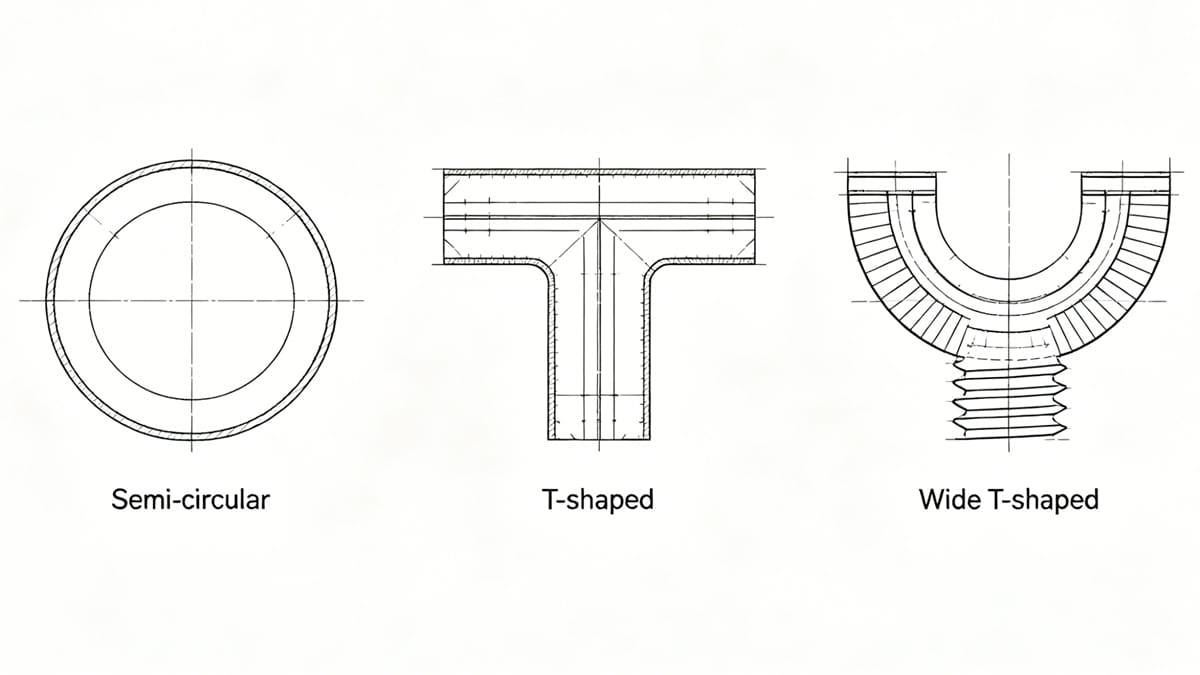
Part Strength Analysis Traditional parts with reinforcing ribs often suffer from sink marks and warpage. GAIM overcomes these issues while ensuring part strength. For the same base plate thickness, a part with a hollow wide T-shaped rib (like in Fig. 1(e)) will be stronger than one with a narrow T-shaped rib, which in turn is stronger than one with a hollow semi-circular rib (like in Fig. 1(a)). While ribs increase stiffness, applying localized stress can significantly weaken the part.
Gas Channel Dimensions The dimensions of the gas channel are closely related to the gas flow direction, as gas always follows the path of least resistance. For a stable Newtonian fluid flowing through a pipe of diameter D, the pressure drop is given by the formula ΔP = 32μVL/D, where μ is viscosity, V is average flow velocity, and L is the length. Since gas viscosity is extremely low (less than 0.1% of resin viscosity), the pressure drop along the length can be ignored, and the resistance is primarily from the resin.
The pressure drop formula for a pseudoplastic fluid is similar. Therefore, by comparing the pressure drop (ΔP) in different directions from the gate (by comparing L and D), one can qualitatively determine the gas's preferred flow direction. The direction with the smaller ΔP is the path the gas will take first. Altering channel dimensions changes the pressure drop, thereby controlling gas flow and impacting part quality.
금형 설계
Since GAIM uses relatively low injection pressure and clamping force, molds can be made from standard mold steels as well as lighter alloys like zinc-based alloys and forged aluminum.
The mold design for GAIM is similar to conventional injection molding. However, defects caused by poor mold or part structure cannot be corrected by adjusting process parameters; the design itself must be modified. The general design principles of conventional molding still apply, with the following specific considerations:
- Avoid Jetting: While GAIM is trending towards thin-wall and special-shaped tubular parts, it is still primarily used for large-volume cavities. High shear stress at the gate can cause melt fracture phenomena like jetting. This can be mitigated by increasing the gate size or placing the gate in a thinner section of the part.
- Cavity Design: Due to the difficulty in consistently controlling parameters like short-shot volume and gas injection pressure, a single-cavity mold is generally recommended, especially for high-quality parts. If a multi-cavity mold is used, a balanced runner system is essential.
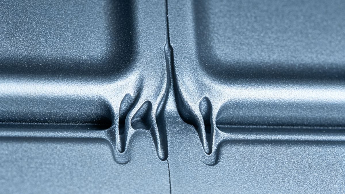
- Gate Design: Typically, only one gate is used. Its position must ensure the melt fills the cavity uniformly during the short shot to avoid jetting. If the gas needle is located in the machine nozzle or runner system, the gate must be large enough to prevent the melt from solidifying before gas injection. A common issue is gas penetrating from the intended channel into thin sections, creating "gas fingering" on the surface. This is often caused by improper gate size and gas delay time and must be avoided.
- Runner Geometry: The runner geometry should be symmetrical or unidirectional relative to the gate, and the gas flow direction must be the same as the molten resin flow direction.
- Overflow Design: The mold should include an overflow space to regulate flow balance and achieve the desired hollow channel.
Gas assisted injection molding technology is widely used in industries such as home appliances, automotive, furniture, and office supplies. Its future development points towards improving dimensional stability, manufacturing high-quality thin-wall parts, producing special-shaped tubes, and replacing metal components in the automotive industry.
-150x150.jpg)