Introduction
Surface defects in injection-molded parts are not merely aesthetic concerns—they often reflect deeper issues in melt flow behavior1, thermal management2, or mold geometry3. Common visible flaws include:
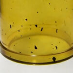
- Dark spots (halo effect) near gates
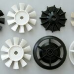
- Gloss inconsistency or haze zones
- Surface wrinkling, commonly called “orange peel”
These defects typically appear near the gate or behind sharp corners—regions where melt front stability is compromised. In this article, we break down the physics behind each defect and provide actionable, evidence-based solutions grounded in both mold design and process engineering.
✅ Pro Tip: Always start diagnosis with a defect location map—most surface issues are spatially correlated with flow path, pressure drop, or thermal gradient.
Dark Spots (Halo Effect) — The “Invisible Skin Slip”
📌 What It Looks Like
A diffuse, grayish ring around the gate—resembling a solar halo—especially prominent when molding high-viscosity resins like PC, PMMA, or ABS.
⚙️ Root Cause
During early filling, the cooled skin layer on the cavity wall is displaced by the faster-moving core melt—a phenomenon known as surface layer slippage. Contrary to popular belief, this occurs primarily in the initial injection phase, not during packing.
Key contributing factors:
- High front-end melt velocity at gate entry
- Low melt temperature → steep viscosity gradient
- Low mold temperature → premature skin solidification
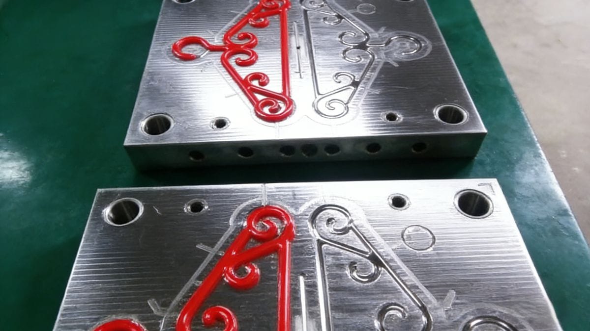
- Sharp gate geometry (e.g., abrupt radii or undersized gate)
📊 Experimental Insight: Studies show that a 20% increase in front-end velocity can raise dark spot incidence by 3.5× (Source: SPE ANTEC 2024).
✅ Proven Solutions
| Approach | Action | Why It Works |
|---|---|---|
| Multi-stage Injection | Start slow (e.g., 20 mm/s), then ramp up after passing critical features (e.g., sharp corners) | Stabilizes melt front velocity; prevents sudden shear-induced skin disruption |
| Thermal Tuning | ↑ Barrel temp (+5–10°C), ↑ back pressure (5–10 MPa) | Improves melt homogeneity and delays skin formation |
| Mold Temperature | ↑ Mold temp by 5–15°C (use for precision) | Extends skin fluidity window for better layer adhesion |
| Gate Redesign | Replace sharp transitions with ≥R0.5 mm radii; use fan-gate or tab-gate for wide parts | Reduces localized turbulence and jetting |
Gloss Variation & Haze Zones — When Texture Doesn’t Transfer
📌 What It Looks Like
Non-uniform surface finish—even with identical mold texture—where some areas appear dull or hazy while others reflect light sharply. Most noticeable on textured surfaces (e.g., leather grain, matte finishes).
⚙️ Root Cause
Gloss depends on how faithfully the melt replicates the mold surface. As melt travels farther from the gate:
- Pressure drops (~5–15 MPa per 10 mm flow path)
- Frontal pressure may fall below the threshold needed to fully press the melt against the cavity wall
- Result: incomplete replication → matte/hazy zones
Additional triggers:
- Abrupt wall thickness changes (>1.5× nominal)
- Insufficient packing pressure/time
- Poor venting → trapped air creates micro-voids that scatter light
📈 Data Point: Gloss deviation correlates strongly with local pressure drop >8 MPa over 30 mm flow length (validated via Moldflow® simulations).
✅ Proven Solutions
| Strategy | Implementation | Expected Outcome |
|---|---|---|
| Packing Optimization | Pack pressure ≥60% of injection pressure; extend pack time by 10–30% | Ensures full cavity contact during solidification |
| Thermal Control | ↑ Melt temp (within material limits) + ↑ mold temp (by 5–15°C) | Lowers viscosity, enhances flow front stability |
| Part Design Review | Avoid abrupt wall transitions; use gradual radii (R ≥ 0.5t) | Prevents flow hesitation & stagnation |
| Venting Enhancement | Add deep vents (0.015–0.025 mm) at flow ends & corners | Eliminates air entrapment that scatters light |
Orange Peel / Surface Wrinkling - The “Frozen Flow Distortion”
📌 What It Looks Like
Wavy, irregular surface texture resembling citrus peel—common in thick-section parts molded4 with high-viscosity resins (e.g., PC/ABS blends).
⚙️ Root Cause
At low injection speeds:
- Outer melt layer solidifies prematurely
- Inner melt continues flowing, dragging the semi-solid skin → buckling/wrinkling
- Once frozen, wrinkles become permanent (unlike flow lines, which can be polished out)
Typically appears at:
- Flow fronts in large cavities
- Behind ribs or bosses
- Near part edges far from gate
⚠️ Critical Note: Over-reliance on high speed alone may cause jetting or air traps—always pair with proper venting and gate geometry.
✅ Proven Solutions
| Method | Details | Why It Works |
|---|---|---|
| Speed & Temp Tuning | Increase injection speed (≥80 mm/s for PC) + raise melt temp (e.g., +10°C) | Keeps skin molten longer; enables uniform deformation |
| Gate Redesign | Use tab/gated runner or overlap gate to avoid direct jetting | Prevents turbulent entry and skin disruption |
| Mold Surface Treatment | Apply fine bead-blast (Ra = 0.8–1.6 µm) to hide minor wrinkles | Masks imperfections without compromising function |
| CAE Validation | Simulate fill front temperature & shear rate (e.g., using Moldflow) | Predicts wrinkle-prone zones pre-manufacturing |
Systematic Diagnostic Workflow (For Engineers)
To eliminate surface defects efficiently, follow this 4-step framework:
- Observe & Locate
→ Map defect position relative to gate, ribs, corners - Diagnose Mechanism
→ Is it flow-induced? Thermal? Structural? - Prioritize Fixes
→ Start with process (fastest ROI), then mold, finally part redesign - Validate & Document
→ Use DOE (Design of Experiments) to quantify impact of each change
✅ Remember: Surface quality is a symptom, not the disease. Fix the root cause—not just the appearance.
Understanding melt flow behavior is crucial for optimizing injection molding processes and reducing defects. ↩
Explore how effective thermal management can enhance product quality and reduce defects in injection molding. ↩
Learn how mold geometry impacts the quality of molded parts and can help prevent defects. ↩
Explore this resource to uncover expert insights and techniques for optimizing thick-section parts in injection molding. ↩