Why Cooling System Design Is Critical in Injection Molding
In Injection Molding1 , an optimally designed mold cooling system is non-negotiable. Plastic parts must solidify to sufficient rigidity before ejection—otherwise, residual stress or external forces cause warpage, sink marks, or dimensional inaccuracies.
Crucially, cooling time consumes 70–80% of the total molding cycle. A precision-engineered cooling system slashes cycle times, boosts throughput, reduces energy costs, and enhances part quality. Conversely, poor cooling design leads to:
- Extended production cycles
- Higher operational costs
- Non-uniform shrinkage and part deformation
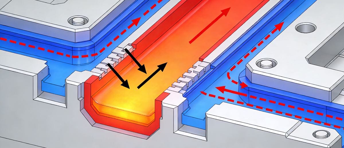
Heat Dissipation Mechanics: Data-Driven Insight
Experimental studies confirm:
- 🔹 95% of heat transfers from molten plastic → mold steel → cooling channels (via conduction & convection)
- 🔹 5% dissipates into ambient air through radiation/convection
Coolant (typically water or glycol mix) absorbs heat via turbulent flow2. Residual heat gradually dissipates through the mold structure post-cycle.
Cooling Time’s Role in the Molding Cycle
The full injection molding cycle comprises:
- Mold closing
- Injection/filling
- Packing/holding
- Cooling (70–80% of total time)
- Ejection
Parts must cool below their Heat Deflection Temperature (HDT)3 before ejection to prevent:
- Warpage from residual stress relaxation
- Deformation from ejector pin pressure
7 Key Factors Influencing Cooling Rate
| Factor | Impact on Cooling Efficiency |
|---|---|
| Part Wall Thickness | Cooling time ∝ (thickness)². Doubling thickness = 4× longer cooling |
| Mold Material Conductivity | High-conductivity steels (e.g., beryllium copper inserts) accelerate heat extraction |
| Cooling Channel Layout | Channels closer to cavity, larger diameter, higher density = superior thermal control |
| Coolant Flow Rate | Turbulent flow (Re > 4,000) maximizes convective heat transfer |
| Coolant Properties | Low viscosity + high thermal conductivity + lower temp = optimal performance |
| Plastic Material | High thermal conductivity (e.g., filled nylons) or low specific heat = faster cooling |
| Processing Parameters | Higher melt/mold temps or lower ejection temp = extended cooling requirement |
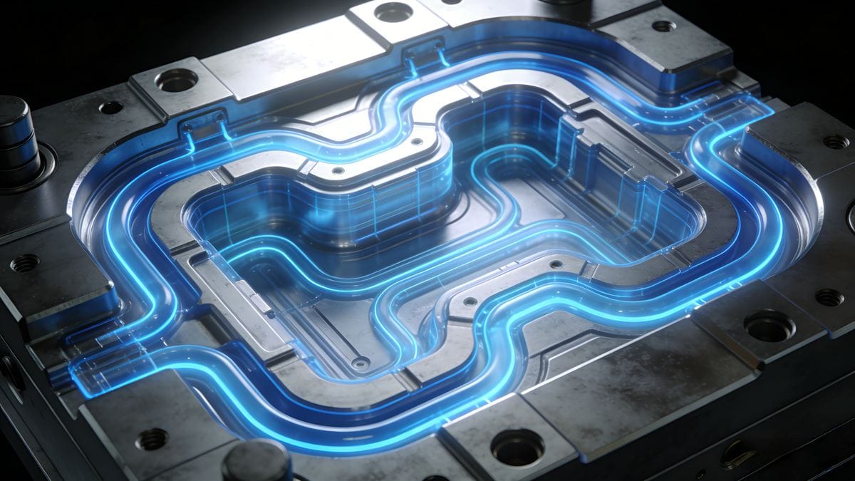
[Image: Comparison graphic – uniform vs. non-uniform cooling channel layout4s with thermal simulation overlay. Alt text: "Cooling channel design impact: uniform layout prevents warpage in thick-walled plastic components"]
Essential Cooling System Design Rules (SEO-Optimized Checklist)
✅ Uniformity First: Position channels symmetrically relative to cavity surfaces to prevent thermal gradients.
✅ Proximity Matters: Maintain 1–1.5× channel diameter distance from cavity surface (e.g., 12mm channel → 12–18mm spacing).
✅ Standardize Components: Use ISO-standard channel diameters (e.g., 8mm, 10mm, 12mm) for machining ease and maintenance.
✅ Flow Optimization: Design for turbulent flow; avoid dead zones with proper inlet/outlet placement.
✅ Material-Specific Tuning: Adjust channel density for thick sections or high-heat plastics (e.g., PEEK, PSU).
✅ Thermal Simulation: Validate layout with Moldflow® or similar CAE tools pre-manufacturing.
✅ Maintenance Access: Include quick-connect fittings and corrosion-resistant materials (e.g., stainless steel lines).
Final Takeaway
Mastering cooling system design transforms molding efficiency. By aligning channel geometry, coolant dynamics, material science, and thermal simulation, manufacturers achieve:
✨ Shorter cycles
✨ Higher part consistency
✨ Reduced scrap rates
✨ Sustainable cost savings
Optimize your mold cooling strategy today—because every second saved in cooling multiplies across thousands of production cycles.
Explore this resource to discover essential techniques and innovations that enhance injection molding efficiency and part quality. ↩
Understand how turbulent flow maximizes heat transfer and improves cooling efficiency. ↩
Learn how HDT affects part quality and performance during the injection molding process. ↩
Explore the critical role of channel design in achieving uniform cooling and preventing defects. ↩