Draft Angle & Wall Thickness Guidelines for Injection Molded Parts
Optimizing Design for Manufacturability, Quality, and Cost Efficiency
When designing plastic parts for injection molding, two critical geometric parameters—draft angle and wall thickness—directly impact moldability, part quality, cycle time, and tooling longevity. Poor choices can lead to ejection failures, warpage, sink marks, or cosmetic defects. This guide consolidates industry best practices, material-specific recommendations, and design rules of thumb to help you avoid common pitfalls.
1. Draft Angle (Mold Release Angle)
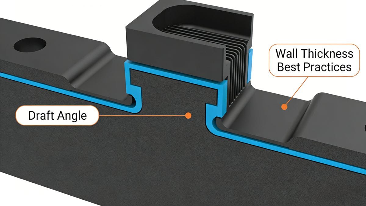
Draft angle—the intentional taper applied to vertical surfaces—is essential for smooth part ejection from the mold cavity and core. Without sufficient draft, parts may stick, drag, or get damaged during demolding.
Typical Draft Angles by Material
| Material | Cavity (a₁) | Core (a₂) |
|---|---|---|
| Nylon (unfilled) | 20′–40′ | 25′–40′ |
| Nylon (reinforced) | 20′–50′ | 20′–40′ |
| Polyethylene (PE) | 25′–45′ | 20′–45′ |
| Polyoxymethylene (POM) | 35′–1°30′ | 30′–1° |
| Polyether (PPO) | 25′–45′ | 20′–45′ |
| Polycarbonate (PC) | 35′–1° | 30′–50′ |
| Polystyrene (PS) | 35′–1°30′ | 30′–1° |
| Acrylic (PMMA) | 35′–1°30′ | 30′–1° |
| ABS | 40′–1°20′ | 30′–1° |
⚠️ Note: 1° = 60 minutes (′). E.g., 1°30′ = 90′.
Draft angle is not fixed—it depends on:
- Part depth/height
- Surface finish (glossy vs. textured)
- Material shrinkage
- Mold geometry (e.g., undercuts, inserts)
- Production volume (higher volumes tolerate tighter tolerances)
Key Design Rules for Draft Angles
- High-precision, glossy surfaces → Use minimal draft (e.g., 0.5°) to preserve dimensional accuracy.
- Tall/deep features → Apply smaller draft angles (calculated based on height-to-draft ratio).
- High-shrinkage materials (e.g., PP, PE) → Increase draft (≥1° recommended).
- Thick walls → Higher shrinkage → Larger draft needed (≥1°–1.5°).
- Transparent parts (e.g., PS, PC, ABS) → Avoid surface scratches; use ≥2.5°–3° for PS, ≥1.5°–2° for ABS/PC.
- Textured surfaces (e.g., leather grain, sandblasted):
- Draft = 2°–5°, depending on texture depth.
- Deeper textures → larger draft required.
- Interlocking features (e.g., snap-fits, shutoffs): Use 1°–3° on mating surfaces.
- Direction of draft:
- Internal features (holes): Draft expands outward (small end = nominal size).
- External features: Draft tapers inward (large end = nominal size).
- Tolerancing: Draft is typically excluded from dimensional tolerances unless specified.
- Consumer electronics housings:
- Outer cosmetic surfaces: ≥3°
- Non-cosmetic features: 1° standard
- Ribs (<3 mm high): 0.5°
- Ribs (3–5 mm): 1°
- Ribs (>5 mm): 1.5°
- Recesses/cavities: Same as ribs.
(See reference diagrams below for visual guidance.)
2. Wall Thickness Design Principles
Wall thickness affects structural integrity, weight, cost, cooling time, and defect risk (e.g., sink marks, voids, warpage). Optimal thickness balances performance with manufacturability.
General Guidelines
- Ideal range: 1.0–5.0 mm, most commonly 2.0–3.0 mm.
- Minimum wall thickness: ≥ 0.4 mm, but only for non-cosmetic, small-area regions (<100 mm²).
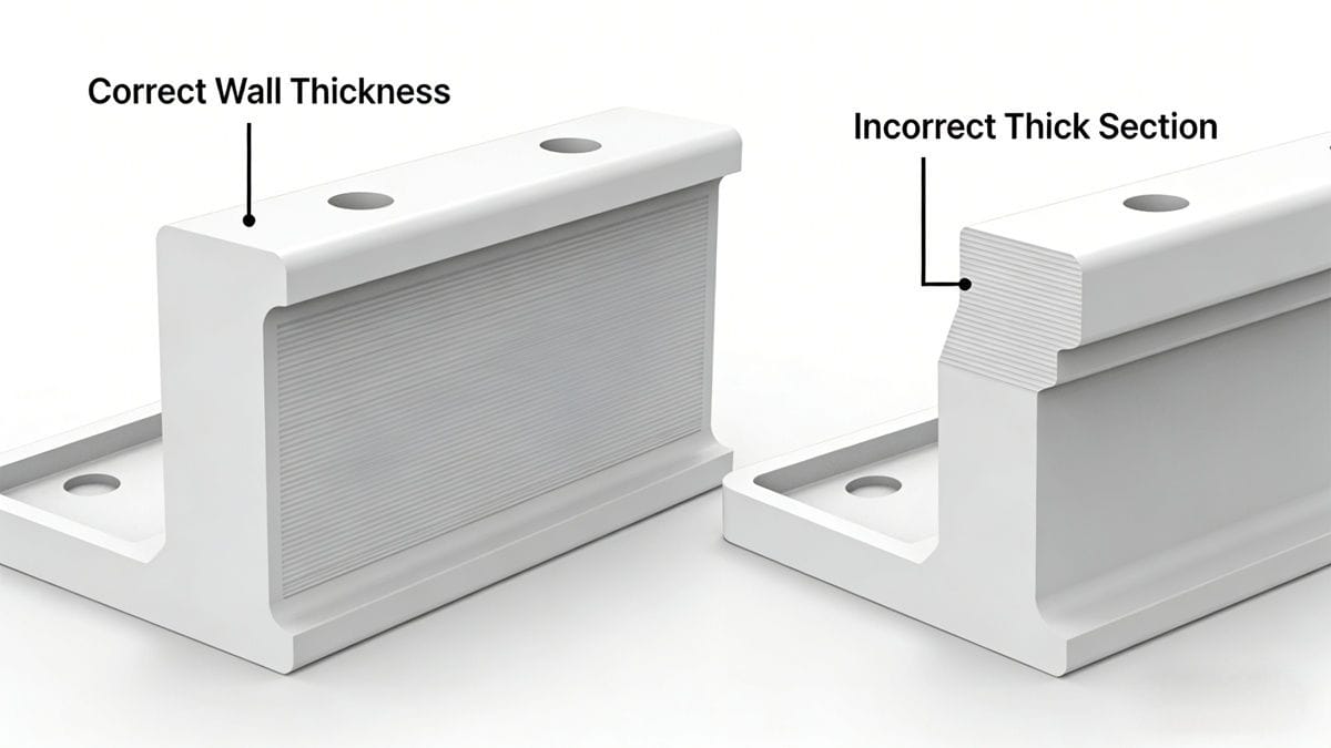
- Uniformity is critical: Avoid abrupt changes (>25% difference) — use gradual transitions or radii to prevent stress concentration and uneven shrinkage.
- Avoid flat plates (unless very small) — prone to warping without ribs or supports.
Material-Specific Minimum & Recommended Wall Thickness (mm)
| Material | Min. Thickness | Small Parts | Medium Parts | Large Parts |
|---|---|---|---|---|
| Nylon (PA) | 0.45 | 0.76 | 1.50 | 2.40–3.20 |
| Polyethylene (PE) | 0.60 | 1.25 | 1.60 | 2.40–3.20 |
| Polystyrene (PS) | 0.75 | 1.25 | 1.60 | 3.20–5.40 |
| Modified PS | 0.75 | 1.25 | 1.60 | 3.2–5.4 |
| PMMA (Acrylic) | 0.80 | 1.50 | 2.20 | 4.00–6.50 |
| Polypropylene (PP) | 0.85 | 1.45 | 1.75 | 2.40–3.20 |
| Polycarbonate (PC) | 0.95 | 1.80 | 2.30 | 3.00–4.50 |
| POM (Acetal) | 0.80 | 1.40 | 1.60 | 2.40–3.20 |
| PSU | 0.95 | 1.80 | 2.30 | 3.00–4.50 |
| ABS | 0.80 | 1.50 | 2.20 | 2.40–3.20 |
| PC+ABS | 0.75 | 1.50 | 2.20 | 2.40–3.20 |
| PVC (rigid) | 1.15 | 1.60 | 1.80 | 3.2–5.8 |
| PVC (flexible) | 0.85 | 1.25 | 1.50 | 2.4–3.2 |
| Polyamide (general) | 0.45 | 0.75 | 1.50 | 2.4–3.2 |
| PPO (Polyphenylene Oxide) | 1.20 | 1.75 | 2.50 | 3.5–6.4 |
| Chlorinated Polyether | 0.90 | 1.35 | 1.80 | 2.5–3.4 |
| Cellulose Acetate | 0.70 | 1.25 | 1.90 | 3.2–4.8 |
| Ethyl Cellulose | 0.90 | 1.25 | 1.60 | 2.4–3.2 |
| Acrylic Copolymers | 0.70 | 0.90 | 2.40 | 3.0–6.0 |
Critical Tips for Wall Thickness Optimization
- Ribs & bosses: Keep wall thickness at ≤50% of main wall to avoid sink marks. Add generous fillets at base.
- Avoid thick sections: Local thick areas cause voids/sink; use coring or ribbing instead.
- Flow path consideration: Thin walls increase flow resistance → may require higher injection pressure or gate redesign.
- Cooling efficiency: Thicker walls = longer cycle times. Uniform thickness improves thermal balance.
Conclusion: Design for Manufacturability (DFM) Wins
Well-designed draft angles and wall thicknesses reduce tooling revisions, scrap rates, and post-molding rework—saving time and money across the product lifecycle.
✅ Pro Tip: Always run mold-flow analysis (e.g., Autodesk Moldflow, SolidWorks Plastics) early in design to validate draft, thickness, and gate locations before tooling.
Let us know in the comments: What’s your biggest challenge with draft angle or wall thickness in your projects? We’d love to share solutions!